23
3.
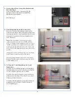
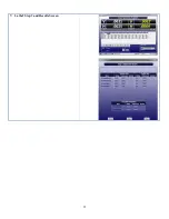
Turn on Scan Plane, Connect the Readout and
Zero the Target
Turn on the scan plane. Connect the R-1308
Readout or turn on the R-1356-2.4ZB PDA
Readout and open Read15.
Zero the target.
4.
Take Measurements for the X Axis (in C)
Move the X down a short distance and note the
value on the readout. Write down the readings and
the distance traveled. Any deviations from zero are
a measure of squareness but also straightness (in
the C direction).
Note: The straightness of X in the Y direction
cannot be measured with the L-702SP with this
setup. To measure the straightness of X in Y, the L-
702SP would have to be mounted to the side of the
headstock spindle and bucked-in to the Y axis with
the A-1519-2.4ZB mounted on the side of the X axis
spindle.
Alternatively, the L-742 Dual Scan or L-743 Triple
Scan® Lasers could be used for this check.
The straightness/flatness data can be recorded in
Machine Tool Geometry Software using the A-910-
2.4ZB USB Receiver.
5.
To Measure Y Axis Straightness (in C) and
Squareness
With the A-1519-2.4ZB attached to the spindle as
described above, move the X axis down so that the
A-1519-2.4ZB is just above the L-702SP.
With the Y axis fully retracted, power on the scan
plane and zero the target. Move the Y axis a short
distance and note the value.
Continue until the spindle is at the end of its travel,
making sure to not hit the L-702SP with the A-
1519-2.4ZB Target.
Summary of Contents for L-702
Page 1: ......
Page 7: ...4 L 702 L 702SP Laser Dimensions...


