32
3.
Start the Read8 program and select Target Setup from the Setup Screen.
Click the
New Target
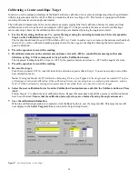
button. The New Target screen displays (see Figure 24).
4.
Click the down arrow next to the Type list box to see a list of targets.
Select the target you want to add. You may enter a new name for the target and the target serial number.
Figure 24—New Target Screen—2-axis Target
4.
Select the calibration factor from the list in the Calibration Constants menu, (+V, -V, +H, -H) then click the
Calibrate button or Press Alt-C.
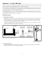
Note: The preferred procedure is to calibrate the vertical axes, both center and slope if appropriate, then rotate the
target in the fixture 90 degrees and calibrate the horizontal axes (see
). If working with a fixture that has a
horizontal micrometer, there is no need to rotate the
target
(see Figure 23).
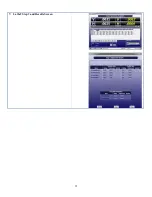
Figure 25—Channel/Port Selection Screen
Figure 26—Calibration Screen
The Select Channel/Port for Target menu displays (see Figure 25). Select the channel or the port to which the target is
attached and click
OK
. The Calibration Screen displays and indicates the Port or Channel selected (see the right arrow
Notes:
Once the first calibration factor is recorded, the program adds the calibration date to the Calibration Constants screen.
The double arrows next to the reading are visible only in Manual Data mode and are not available when actual targets are being
read (see left arrow in
).).
Ensure that you perform each step slowly so that the values have time to register correctly before you press the spacebar.
Summary of Contents for L-702
Page 1: ......
Page 7: ...4 L 702 L 702SP Laser Dimensions...

