7
Preparing for an Alignment
There are several preparations that need to be made before beginning a measurement or alignment process. Ensure that
accurate records are kept for all procedures.
Lathe9 is designed to measure and align the spindle axis of rotation (AOR) to the tailstock, saddle or turret guideways. It
is also used to check the four-axis alignment of the tailstock or subspindle to the headstock AOR. The software fully
compensates for mounting errors of both the laser and target with extremely accurate results.
In lathe alignment, the L-702/L-702SP is mounted in the headstock spindle and aligned to the AOR. The T-261 Target is
then mounted in the tailstock chuck or in a fixture on the saddle, and then the straightness and flatness of the guideways is
measured relative to the L-702/L-702SP laser. The least-squares, best-fit algorithm is used to calculate the slope of the
“best-fit” line for the straightness data. This slope is a measure of the headstock alignment to the lathe guideways.
If the headstock rotation axis (AOR) is parallel (aligned) to the guideways, only then can the tailstock center or a
subspindle AOR be checked for alignment to the headstock AOR. The T-261 offers a live four-axis display of the
tailstock, subspindle or turret centers or AOR relative to the laser beam (headstock AOR).
Hardware Mounting
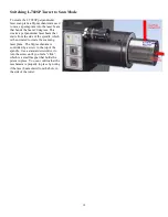
Both the L-702/L-702SP Laser and T-261 Target have a standardized .4995 in. (12.69
mm) mounting stud that simplifies fixturing and that can be removed to adapt the unit to
custom fixtures or other alignment applications. A .500 in. reamed hole that is square to a
face is all that is required to mount the laser/target mounting stud. The mounting stud also
has a ¼-20 threaded hole in the end of it.
Typically, the laser is mounted in the headstock chuck or collet. For large lathes, this may
involve creating a fixture to hold the laser in place. The T-261 is mounted in the tailstock
chuck, subspindle chuck or the turret center.
Maintenance and Cleaning
The spindle to be aligned should be checked thoroughly to ensure that it is clean and working properly. The window on
the T-261 should be clean and free from dirt, thumbprints and other smudges. The same applies to the L-702SP
pentaprism.
Tools and Equipment
Determine all the necessary tools and equipment (other than what Hamar Laser supplies) that will be needed for
performing an alignment, such as torque wrenches, shims, and equipment manuals.
Other Considerations
•
Measure the travel distance of the tailstock, subspindle or turret. This information is necessary for the software setup.
Use only the distance that the unit realistically travels during use, not the full distance of which it is capable.
•
Keep records of all procedures. Log all data file names and keep record copies of all reports and printed data.
Figure 8—L-702 Mounting Stud
Summary of Contents for L-702
Page 1: ......
Page 7: ...4 L 702 L 702SP Laser Dimensions...


