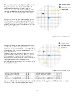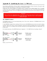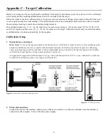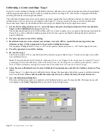
29
Adjustments
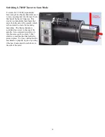
The L-700 laser has centering and angular micrometer adjustments. The beam is emitted from the large hole in the center.
The illustration below shows the location of the various adjustment screws.
Warning!!
Avoid direct exposure to the laser beam while adjusting the laser. Do not stare into the beam.
Manual/Software-Assisted Qualification
To qualify a laser, error correction readings are taken to cancel out mounting and other errors and a set point is calculated.
The laser beam is then adjusted to the set point, making it parallel to/coincident with the desired axis of rotation.
Manual qualifying requires the user to calculate the set point from the error correction readings before adjusting the laser
to that point. A computer program, such as READ8, calculates the set point for the user, and zeroes the display at that
point. The user then adjusts the laser beam to zero. While many users find the software-assisted method slightly easier,
both procedures are essentially the same, and both will result in a qualified laser.
Hardware Requirements
The common equipment required to perform a qualifying procedure would be a target, an L-702 laser, and the spindle or
fixture to hold the laser and target. To measure both the angle and center, a two-axis target with an angle module (the T-
212) or a four-axis simultaneous target (such as the T-261A) is required. If the laser is being qualified to its own mounting
stud axis of rotation, the recommended fixture is the Hamar Laser Model A-801 alignment/calibration fixture.
Each method also has its own additional requirements. The manual procedure requires a readout. The software-assisted
procedure requires a computer and interface and Lathe9, Spindle8 or Read8 software.
Manual Qualifying Procedure
The following procedure explains how to qualify the laser with a four-axis target and a handheld readout. The best way to
do this is to calculate set points for
angle
and adjust the laser angle first. The user then goes back and calculates the
center
set points and adjusts the laser centering.
Setup
1.
Connect the target to the readout.
Plug the target into the readout and power on the readout.
2.
Set the laser and target in the spindle or fixture.
If qualifying to a spindle (or spindle mounting fixture), mount the laser in the spindle and the target in the master part.
(If the beam does not strike the target cell while mounted in the spindle, move the spindle head until the readout
window displays a reading and the
ON TARGET
light is on).
If qualifying the laser to its own mounting stud axis, mount the laser and target facing each other in the A-801
calibration fixture.
Summary of Contents for L-702
Page 1: ......
Page 7: ...4 L 702 L 702SP Laser Dimensions...

