34
Calibrating a Center-and-Slope Target
In order to use the automated features of the Read8 software, calibration for a center-and-slope target must be performed
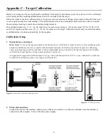
with the target mounted in the A-807 calibration mounting fixture (see Figure 23). This fixture is equipped with both a
centering micrometer and an angle micrometer.
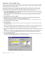
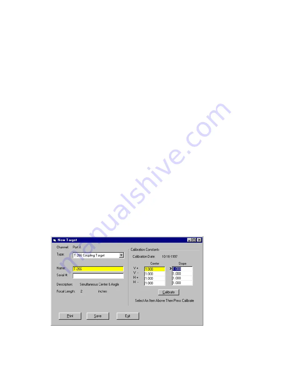
The Calibration Constants menu for center-and-slope targets requires that four calibration factors for center and four
calibration factors for slope be entered (compare with Figure 27). The procedure is the same as that for calibrating a
center-only target, however the calibration factors for slope are obtained by using the angle micrometer.
1.
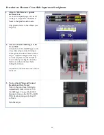
For the first reading, (in this case V+), center the target using the centering micrometer. This corresponds to
Step 1 on the Calibration Screen (see
The display should read close to 0.000 (within ±.005 in.). Center in such a way as to remove the micrometer backlash;
that is, for a
positive
calibration reading, approach zero from a
negative
reading by adjusting the micrometer in a
positive direction.
2.
Press the spacebar to record the reading.
3.
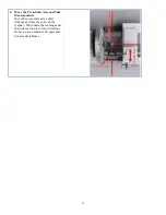
Read the micrometer on the selected axis and move it exactly .025 in., (one full turn) moving in the same
direction as Step 1. This corresponds to Step 2 on the Calibration Screen.
The displayed reading should be close to +.025 for the positive factors and close to –.025 for the negative factors.
4.
Press the spacebar to record the reading.
5.
Re-zero the target.
Turn the micrometer .025 in. (one full turn) in the direction
opposite
that in Step 3. You are now ready to record the
next calibration factor.
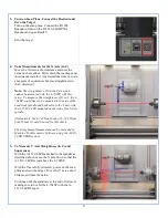
Note: If using the Model A-807 Calibration Mounting Fixture, (see
) the target must be rotated 90° before
performing a horizontal calibration. If the calibration fixture you are using has two centering micrometers, such as
the T-230, the horizontal centering micrometer may be used and there is no need to rotate the target.
6.
Select the next calibration factor from the Calibration Constants menu, and click the Calibrate button or Press
Alt-C.
Follow Steps 1-5 to obtain the next calibration factor. Repeat this procedure until all the necessary calibration factors
have been obtained.
Ensure that the calibration factors for slope are obtained by using the angle micrometer.
7.
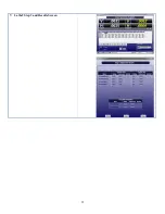
Save the calibration information.
When the calibration procedure is completed, click the
Save
button to save the target profile. This target name will
now display in the
Select Targets to Use
section of the Target Setup Screen.
Figure 27
–
New Target Screen – 4-axis Target
Summary of Contents for L-702
Page 1: ......
Page 7: ...4 L 702 L 702SP Laser Dimensions...

