10
Subject to change without notice
Basic signal measurement
Signals which can be measured
The following description pertains to analog and digital ope-
ration. The different specifications in both operating modes
should be kept in mind.
The oscilloscope HM2008 can display all repetitive signals
with a fundamental repetition frequency of at least 200 MHz.
The frequency response is 0 to 200 MHz (–3 dB). The vertical
amplifi ers will not distort signals by overshoots, undershoots,
ringing etc.
Simple electrical signals like sine waves from line frequency
ripple to hf will be displayed without problems. However, when
measuring sine waves, the amplitudes will be displayed with
an error increasing with frequency. At 120 MHz the amplitude
error will be around –10 %. As the bandwidths of individual
instruments will show a certain spread (the 200 MHz are a
guaranteed minimum) the actual measurement error for sine
waves cannot be exactly determined.
Pulse signals contain harmonics of their fundamental fre-
quency which must be represented, so the maximum useful
repetition frequency of nonsinusoidal signals is much lower
than 200 MHz (5 to 10 times). The criterion is the relationship
between the rise times of the signal and the scope; the scope’s
rise time should be
<
1/3 of the signal’s rise time if a faithful
reproduction without too much rounding of the signal shape
is to be preserved.
The display of a mixture of signals is especially diffi cult if it con-
tains no single frequency with a higher amplitude than those of
the other ones as the scope’s trigger system normally reacts to
a certain amplitude. This is e.g. typical of burst signals. Display
of such signals may require using the HOLD-OFF control.
Composite video signals may be displayed easily as the instru-
ment has a TV SYNC separator.
The maximum sweep speed of 2 ns/cm allows suffi cient time
resolution, e.g. a 200 MHz sine wave will be displayed one
period per 2.5 cm. The vertical amplifi er inputs may be DC or
AC coupled. Use DC coupling only if necessary and preferably
with a probe.
Low frequency signals when AC coupled will show tilt (AC low
frequency – 3 dB point is 1.6 Hz), so if possible use DC coupling.
Using a probe with 10:1 or higher attenuation will lower the
–3 dB point by the probe factor. If a probe cannot be used due
to the loss of sensitivity DC coupling the scope and an external
large capacitor may help which, of course, must have a suffi cient
DC rating. Care must be taken, however, when charging and
discharging a large capacitor.
DC coupling is preferable with all signals of varying duty cycle,
otherwise the display will move up and down depending on the
duty cycle. Of course, pure DC can only be measured with DC
coupling.
The readout will show which coupling was chosen: = stands
for DC, ~ stands for AC. For hf measurement an internal 50 Ω
terminator can be activated which is indicated by an Ω-symbol
in the readout.
Amplitude of signals
In contrast to the general use of rms values in electrical engi-
neering oscilloscopes are calibrated in Vpp as that is what is
displayed.
Derive rms from V
pp
: divide by 2.84. Derive V
pp
from rms: mul-
tiply by 2.84.
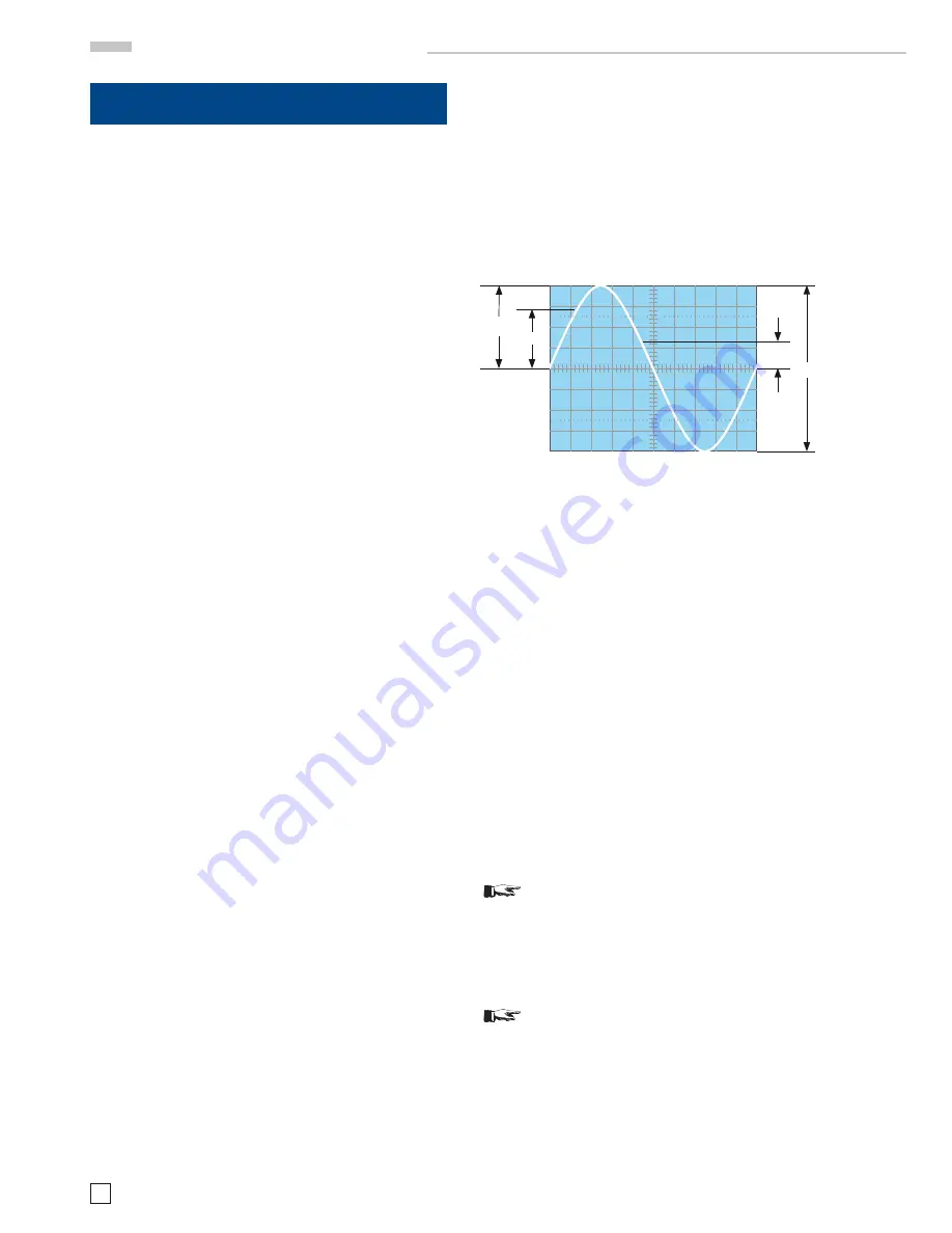
Values of a sine wave signal
V
rms
= rms value
V
pp
= pp – value
V
mom
= momentary value, depends on time vs. period.
The minimum signal for a one cm display is 1 mV
pp
±5 % provi-
ded 1 mV/cm was selected and the variable is in the calibrated
position.
The available sensitivities are given in mV
pp
or V
pp
. The cursors
allow to indicate the amplitudes of the signals immediately on
the readout as the attenuation of probes is automatically taken
into account. Even if the probe attenuation was selected manu-
ally this will be overridden if the scope identifi es a probe with
an identifi cation contact as different. The readout will always
give the true amplitude.
It is important that the variable be in its calibrated position. The
sensitivity may be continuously decreased by using the variable
(see Controls and Readout). Each intermediate value between
the calibrated positions 1–2–5 may be selected. Without using
a probe thus a maximum of 100 V
PP
may be displayed (20 V/div
x 8 cm screen x 2.5 variable).
Amplitudes may be directly read off the screen by measuring
the height and multiplying by the V/div. setting.
STOP
Please note: Without a probe the maximum permis-
sible voltage at the inputs must not exceed 250 Vp
irrespective of polarity.
In case of signals with a DC content the peak value DC + AC
peak must not or –250 V
p
. Pure AC of up to 500 V
pp
is
permissible.
STOP
If probes are used their possibly higher ratings are
only usable if the scope is DC coupled.
In case of measuring DC with a probe while the scope input is
AC coupled the capacitor in the scope input will see the input
DC voltage as it is in series with the internal 1 MΩ resistor.
This means that the maximum DC voltage (or DC + peak AC) is
that of the scope input, i.e. 250 V
P
! With signals which contain
DC and AC the DC content will stress the input capacitor while
the AC content will be divided depending on the AC impedance
B a s i c s i g n a l m e a s u r e m e n t
V
p
V
rms
V
mom
V
pp


