Subject to change without notice
27
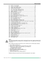
Table of Contents
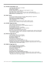
(1)
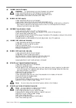
R1008: +141 Volt supply. ............................................................................ 29
(2)
R1016: +12 Volt supply. .............................................................................. 29
(3)
VR7000: Trace Rotation Check. .................................................................. 29
(4)
R1004 : CRT minimum intensity. ................................................................ 29
(5)
R712RT maximum intensity. ....................................................................... 29
(6)
R712: Mean Y-plate Potential Channel I. .................................................... 29
(7)
R714: Mean Y-plate Potential Channel II. ................................................... 29
(8)
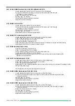
RV6021 : Astigmatism correction. .............................................................. 31
(9)
R640: Y-Gain CH I. ...................................................................................... 31
(10)
R122: FET operating point CH I. ................................................................. 31
(11)
R203: Invert-Balance CH I. ......................................................................... 31
(12)
R177: Variable-Balance CH I. ...................................................................... 31
(13)
R139: 100Hz Squarewave 5mV/div CH I. ................................................... 32
(14)
R134: 100Hz Squarewave 1mV/div Adjustment CH I. ............................... 33
(15)
R658: Y-Gain CH II. ..................................................................................... 33
(16)
R422: FET operating point CH II. ................................................................ 33
(17)
R503: Invert-Balance CH II. ........................................................................ 33
(18)
R477: Variable-Balance CH II. ..................................................................... 33
(19)
R439: 100Hz Squarewave 5mV/div CH II. .................................................. 33
(20)
R434: 100Hz Squarewave 1mV/div CH II. .................................................. 33
(21)
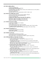
RV2005 (A), RV2006 (C), CV2000 (D) and CV2001 (B): Y-Final Amplifier. .. 35
(22)
Y-Amplifier Bandwidth Check. .................................................................... 35
(23)
C113/111/102/105: Attenuator Compensation CH I. .................................. 35
(24)
C413/411/402/405: Attenuator Compensation CH II. ................................. 35
(25)
R663: ADDition/Offset. ............................................................................... 37
(26)
RV2417 (A), RV2418 (B): Overscan. ........................................................... 37
(27)
RV3519: Sweep start voltage. .................................................................... 37
(28)
RV2225: X-Magnification x1. ...................................................................... 37
(29)
RV2260: X-Symmetry. ................................................................................ 37
(30)
RV3591 (A)/3589 (C), CV3511 (B): Time base. ........................................... 37
(31)
RV2234: X-Magnification x10. .................................................................... 39
(32)
R624: XY-Gain ............................................................................................. 39
(33)
RV3293: Trigger-Symmetry ......................................................................... 39
(34)
R612: DC-Triggering CH I. .......................................................................... 39
(35)
R603: DC-Triggering CH II. ......................................................................... 39
(36)
RV2301 (A), 4322 (B): Component Tester Y-Position and Tilt. .................... 41
(37)
VR8940: Calibrator Output. ........................................................................ 41
(38)
Trigger Filter Check. .................................................................................... 41
(39)
Triggerbandwidth Check. ............................................................................ 41
(40)
External Trigger Check. ............................................................................... 41
(41)
Video Trigger Check. ................................................................................... 42
NOTE
The adjustment procedures assume that the instrument had once been properly adjusted in the
factory and adjustments are required due to temperature drift or the replacement of defective
components.
Before starting each adjustment procedure, set the oscilloscope to the following basic settings:
•
Press POWER pushbutton (in!).
•
Release all other pushbuttons (out!) except AC/DC input coupling.
•
Rotate the three variable controls (TIME/DIV. and VOLTS/DIV.) to
their (calibrated) detent positions.
•
Set TIME/DIV. switch to 50µs/div.
•
Set both VOLTS/DIV switches to 5mV/div.
•
Rotate the HOLD OFF knob fully counterclockwise.
•
Trigger coupling set to AC.
•
Set all other controls to their midrange positions.
If different settings are required, they are mentioned particularly for each subject.
Summary of Contents for HM 303-4
Page 3: ...Subject to change without notice 2...
Page 5: ...Subject to change without notice 4 Y Preamplifier CH I YP Board...
Page 6: ...Subject to change without notice 5 Y Preamplifier CH II YP Board...
Page 7: ...Subject to change without notice 6 Y Intermediate Amplifier and Trigger Amplifier YP Board...
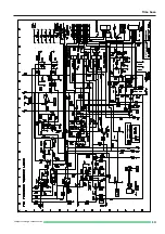
Page 8: ...Subject to change without notice 7 YPA Board Top side...
Page 9: ...Subject to change without notice 8 YPA Board Top side...
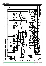
Page 10: ...Subject to change without notice 9 XY Amplifier YF Amplifier OS Circuit...
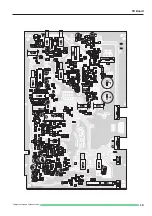
Page 11: ...Subject to change without notice 10 XY Board Top side...
Page 12: ...Subject to change without notice 11 XY Board Top side...
Page 13: ...Subject to change without notice 12 Sync Amplifier...
Page 14: ...Subject to change without notice 13 Time base...
Page 15: ...Subject to change without notice 14 Sweep Generator...
Page 16: ...Subject to change without notice 15 TB Board...
Page 17: ...Subject to change without notice 16 CRT Board...
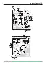
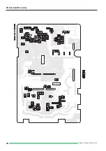
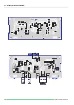
Page 18: ...Subject to change without notice 17 CRT Board Top and Bottom side...
Page 20: ...Subject to change without notice 19 PS Board Top side...
Page 21: ...Subject to change without notice 20 PS Board Bottom side...
Page 22: ...Subject to change without notice 21 Component tester Calibrator...
Page 23: ...Subject to change without notice 22 CCT Board Top and Bottom side...
Page 24: ...Subject to change without notice 23 Front control board...
Page 25: ...Subject to change without notice 24 Front Control board Top and Bottomside...
Page 26: ...Subject to change without notice 25 Adjustment Procedure...
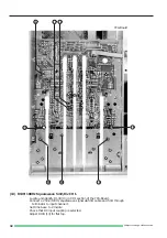
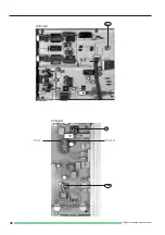
Page 31: ...Subject to change without notice 30 10 12 7 11 9 8 YPA Board PS Board...
Page 35: ...Subject to change without notice 34 A C D B 24 B D C A 23 YPA Board 21 A D B C...
Page 39: ...Subject to change without notice 38 YPA Board 35 32 34 31 33 TB Board XY Board...
Page 41: ...Subject to change without notice 40 37 36B Pin 14 Pin 1 CT Board 36A XY Board...

