Subject to change without notice
35
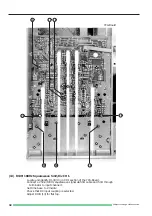
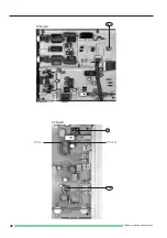
(21) RV2005 (A), RV2006 (C), CV2000 (D) and CV2001 (B):
Y-Final Amplifier.
Connect a 1MHz squarewave signal of 25mV via 50
Ω
cable and 50
Ω
through termination
to input CH I.
Check that DC input coupling is selected.
Set time base to 0.2µs/div.
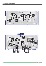
Locate and identify the adjustment points RV2005 (21A), RV2006 (21B), CV2000 (21C) and
CV2001 (21D) on XY-Board.
As the capacitive influence of the cabinet is of importance, a metal sheet above the Y-final
amplifier section is required.
Adjust RV2005 (21A) and CV2001 (21B) for flat top, RV2006 (21C) and CV2000 (21D) for fast
leading edge with minimum overshoot.
Repeat until optimum is obtained.
Check channel II under the same conditions.
(22) Y-Amplifier Bandwidth Check.
Connect a 40mVpp/50kHz sinewave signal from a constant amplitude generator via
a 50
Ω
throughtermination to the input of channel I.
Adjust the generator amplitude for 8 div. display height on the screen.
Increase the generator frequency until the signal is displayed with 5.6 div. height ( -3dB).
Repeat the adjustment under item 21), if the frequency reading on the generator shows a value
less than 30MHz.
Press CHI/II-TRIGI/II pushbutton (in!).
Connect a 40mVpp/50kHz sinewave signal from a constant amplitude generator via
a 50
Ω
throughtermination to the input of channel II.
Adjust the generator amplitude for 8 div. signal height displayed on the screen.
Increase the generator frequency until the signal is displayed with 5.6 div. height ( -3dB).
Repeat the adjustments under item 21), if the frequency reading on the generator shows
a value less than 30MHz.
(23) C113/111/102/105: Attenuator Compensation CH I.
Locate and identify trimmers VC102-113 for CH I on YPA-Board.
Check that DC input coupling is selected.
Check that input attenuator CH I is in 5mV/div setting.
Set time base switch to 0.5ms/div.
Set amplitude calibrator to 1kHz and connect a 2:1 pre-attenuator via 50
Ω
cable to input of CH I.
Set calibrator output voltage to 80mVpp (40mVpp at the 2:1 pre-attenuator output,
if terminated with 1M
Ω
).
Adjust trimmer in pre-attenuator for flat squarewave top. This adjustment must not be changed
during the following procedure.
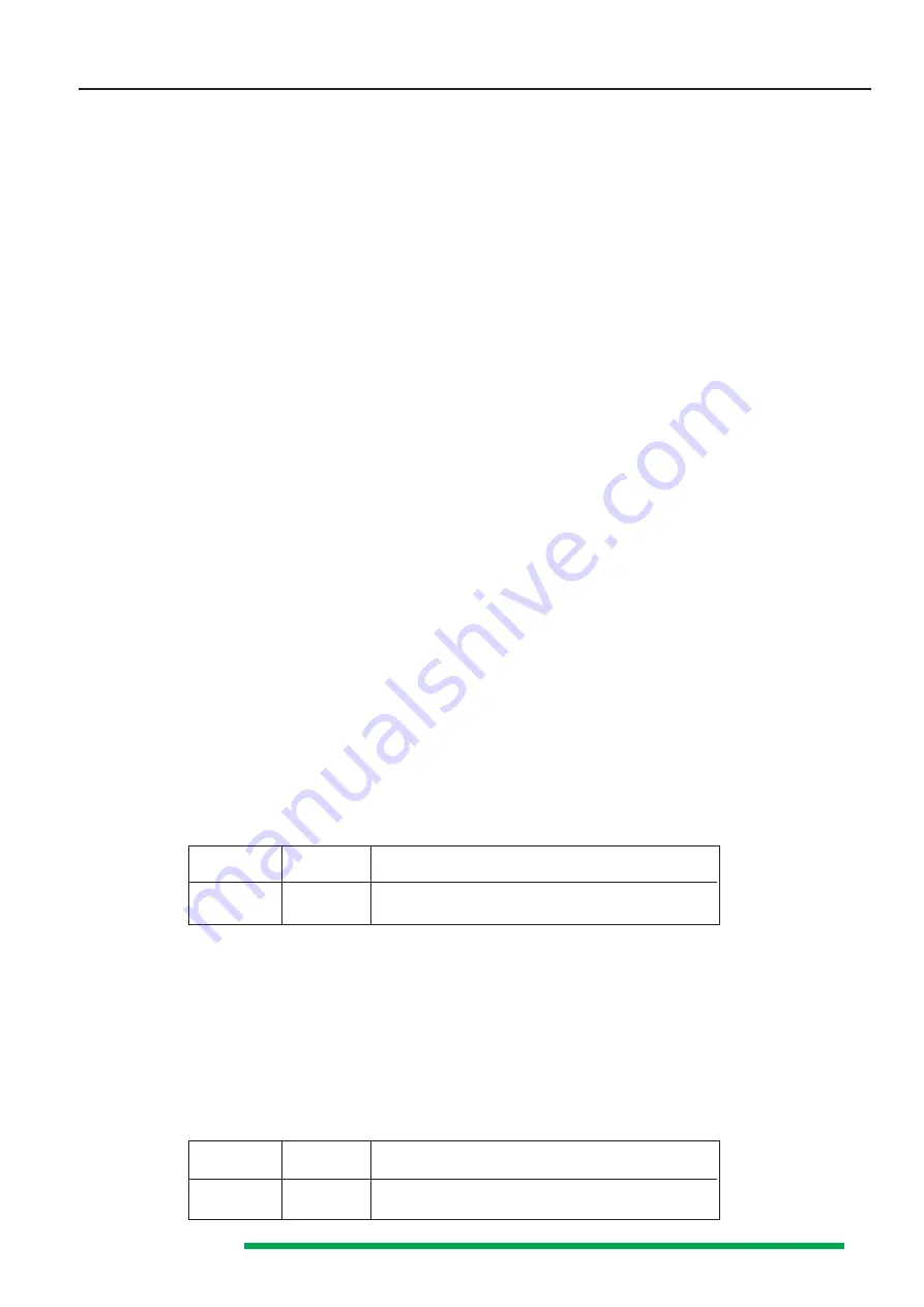
Adjust compensation as listed in the table below:
Scope
Input
Adjustment
Input
Atten.
CH I
250mVpp
50mV/div
A (VC111) flat top + B (VC113) leading edge
2.5Vpp
0.5V/div
C (VC102) flat top + D (VC105) leading edge
(24) C413/411/402/405: Attenuator Compensation CH II.
Locate and identify trimmers VC402-413 for CH II on YPA-Board.
Check that DC input coupling is selected.
Check that input attenuator CH II is in 5mV/div setting.
Set time base switch to 0.5ms/div.
Set amplitude calibrator to 1kHz and connect a 2:1 pre-attenuator via 50
Ω
cable to input of CH II.
Set calibrator output voltage to 80mVpp (40mVpp at the 2:1 pre-attenuator output,
if terminated with 1M
Ω
).
Adjust trimmer in pre-attenuator for flat squarewave top. This adjustment must not be
changed during the following procedure.
Adjust compensation as listed in the table below:
Scope
Input
Adjustment
Input
Atten.
CH II
250mVpp
50mV/div
A (VC411) flat top + B (VC413) leading edge
2.5Vpp
0.5V/div
C (VC402) flat top + D (VC405) leading edge
Summary of Contents for HM 303-4
Page 3: ...Subject to change without notice 2...
Page 5: ...Subject to change without notice 4 Y Preamplifier CH I YP Board...
Page 6: ...Subject to change without notice 5 Y Preamplifier CH II YP Board...
Page 7: ...Subject to change without notice 6 Y Intermediate Amplifier and Trigger Amplifier YP Board...
Page 8: ...Subject to change without notice 7 YPA Board Top side...
Page 9: ...Subject to change without notice 8 YPA Board Top side...
Page 10: ...Subject to change without notice 9 XY Amplifier YF Amplifier OS Circuit...
Page 11: ...Subject to change without notice 10 XY Board Top side...
Page 12: ...Subject to change without notice 11 XY Board Top side...
Page 13: ...Subject to change without notice 12 Sync Amplifier...
Page 14: ...Subject to change without notice 13 Time base...
Page 15: ...Subject to change without notice 14 Sweep Generator...
Page 16: ...Subject to change without notice 15 TB Board...
Page 17: ...Subject to change without notice 16 CRT Board...
Page 18: ...Subject to change without notice 17 CRT Board Top and Bottom side...
Page 20: ...Subject to change without notice 19 PS Board Top side...
Page 21: ...Subject to change without notice 20 PS Board Bottom side...
Page 22: ...Subject to change without notice 21 Component tester Calibrator...
Page 23: ...Subject to change without notice 22 CCT Board Top and Bottom side...
Page 24: ...Subject to change without notice 23 Front control board...
Page 25: ...Subject to change without notice 24 Front Control board Top and Bottomside...
Page 26: ...Subject to change without notice 25 Adjustment Procedure...
Page 31: ...Subject to change without notice 30 10 12 7 11 9 8 YPA Board PS Board...
Page 35: ...Subject to change without notice 34 A C D B 24 B D C A 23 YPA Board 21 A D B C...
Page 39: ...Subject to change without notice 38 YPA Board 35 32 34 31 33 TB Board XY Board...
Page 41: ...Subject to change without notice 40 37 36B Pin 14 Pin 1 CT Board 36A XY Board...


