Subject to change without notice
41
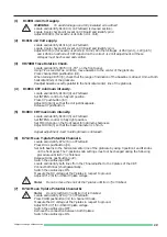
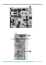
(36) RV2301 (A), 4322 (B): Component Tester Y-Position and Tilt.
Release all pushbuttons (out!).
Press COMPONENT TESTER pushbutton (in!).
Locate and identify RV2301 (36A) on XY-Board.
Adjust RV2301 (36A) to shift the approx. 8 div. horizontal component tester trace to the
horizontal center of the CRT graticule.
Locate and identify RV4322 (36B) on CC-Board.
Set up the instrument on a table in normal operating conditions to avoid misadjustment due
to the influence of the earth magnetic field.
Adjust RV4322 (36B) in such a way that the trace is parallel to the horizontal graticule center line
and not tilt. This adjustment
(37) VR8940: Calibrator Output.
Locate and identify VR8940 (37) on CC-Board.
Connect a digital multimeter to the 0.2Vpp calibrator output.
Set up the digital multimeter for DC measurement in a suited sensitivity setting.
Locate and identify IC8903 on CC-Board.
Connect pin 1 and pin 14 of IC8903 galvanically together.
Adjust VR8940 (37) for exactly 0.2V DC.
Check 2V calibrator output.
Remove the connection between pin 1 and pin 14 of IC8903.
Connect a 10:1 probe to the 0.2Vpp calibrator output and connect it to the CH I input of the scope.
Release all pushbuttons (out!).
Select CH I DC input coupling.
Set attenuator CH I to 5mV/div (calibrated detent).
Set time base to 0.2ms/div.
Now approximately 2 signal periods should be visible on the screen.
Press 1kHz/1MHz pushbutton (in!).
Set time base to 0.5µs position.
Check 1MHz calbrator signal.
Please note:
Neither the calibrator frequency nor the pulse duty factor are specified.
(38) Trigger Filter Check.
Set time base to 1ms/div.
Connect a 1kHz sinewave signal of 40mVpp amplitude to input CH I and check for full
screen deflection.
Set input attenuator CH I to 50mV/div and check for 8mm display height.
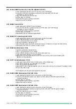
Select trigger coupling from AC to DC and LF. The signal must always trigger .
Set sinewave generator to 50kHz and 40mV output amplitude and check for 8mm display height.
Select trigger coupling from AC to DC. The signal must always trigger.
Select LF trigger coupling. Now the signal should not trigger.
(39) Triggerbandwidth Check.
Set time base to 0.05µs/div, time base variable to CAL position.
Set input coupling switch CH I to DC.
Set trigger coupling to AC.
Release AUTO/NORM pushbutton (out!).
Set input attenuator CH I to 5mV/div.
Connect a 100MHz sinewave signal to input CH I.
Adjust generator output for 5mm display height.
The signal must be triggered.
(40) External Trigger Check.
Set time base to 20µs/div.
Set input attenuator CH I to 0.1V/div.
Connect a 50 kHz sinewave signal via a 50-Ohm through terminator with an amplitude of
280mVpp (100mVrms) to input CH I and check for 2.8div display height.
Set LEVEL to midrange position.
Check that the Trigger-LED is ON.
Press EXT. pushbutton. The Trigger-LED (TR) should now be OFF.
Summary of Contents for HM 303-4
Page 3: ...Subject to change without notice 2...
Page 5: ...Subject to change without notice 4 Y Preamplifier CH I YP Board...
Page 6: ...Subject to change without notice 5 Y Preamplifier CH II YP Board...
Page 7: ...Subject to change without notice 6 Y Intermediate Amplifier and Trigger Amplifier YP Board...
Page 8: ...Subject to change without notice 7 YPA Board Top side...
Page 9: ...Subject to change without notice 8 YPA Board Top side...
Page 10: ...Subject to change without notice 9 XY Amplifier YF Amplifier OS Circuit...
Page 11: ...Subject to change without notice 10 XY Board Top side...
Page 12: ...Subject to change without notice 11 XY Board Top side...
Page 13: ...Subject to change without notice 12 Sync Amplifier...
Page 14: ...Subject to change without notice 13 Time base...
Page 15: ...Subject to change without notice 14 Sweep Generator...
Page 16: ...Subject to change without notice 15 TB Board...
Page 17: ...Subject to change without notice 16 CRT Board...
Page 18: ...Subject to change without notice 17 CRT Board Top and Bottom side...
Page 20: ...Subject to change without notice 19 PS Board Top side...
Page 21: ...Subject to change without notice 20 PS Board Bottom side...
Page 22: ...Subject to change without notice 21 Component tester Calibrator...
Page 23: ...Subject to change without notice 22 CCT Board Top and Bottom side...
Page 24: ...Subject to change without notice 23 Front control board...
Page 25: ...Subject to change without notice 24 Front Control board Top and Bottomside...
Page 26: ...Subject to change without notice 25 Adjustment Procedure...
Page 31: ...Subject to change without notice 30 10 12 7 11 9 8 YPA Board PS Board...
Page 35: ...Subject to change without notice 34 A C D B 24 B D C A 23 YPA Board 21 A D B C...
Page 39: ...Subject to change without notice 38 YPA Board 35 32 34 31 33 TB Board XY Board...
Page 41: ...Subject to change without notice 40 37 36B Pin 14 Pin 1 CT Board 36A XY Board...

