33
Indroduction of the HM8134-3
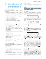
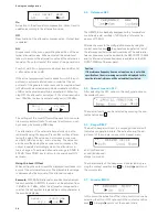
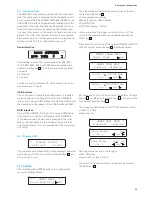
The modulation is turned on by pressing the context sensi-
tive key
5
below the string OFF. One time for turning the
internal source on (INT) and a second time for turning the
external source on (EXT). The active source is pointed out
by a triangle beside the option.The indicator LED of the
MOD.OUTPUT is lighting.
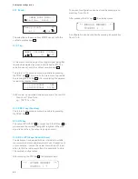
Pressing the context sensitive key
5
once again, the mo-
dulation will be deactivated (OFF).
The return to the previous menu is possible by pressing
the PREV. key
3
.
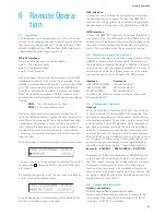
With external AM activated, the only modifiable op-
tion is the modulation depth (see paragraph ”Amplitude
modulation“).
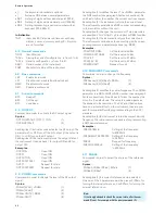
The external modulation frequency for AM must be in the
range: 10 Hz to 50 kHz
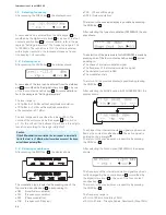
With external FM or PM activated, several cases are
possible:
❙DC coupled (DC – 150 kHz)
❙AC coupled (10 Hz – 150 kHz)
❙Deviation (see corresponding paragraph)
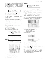
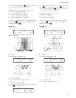
Example 1:
CH1: modulation: first pulse width 150 s
second pulse width 1.1 ms
period 2.5 ms (Fmod: 400 Hz)
CH2 moduled signal (deviation: 2 kHz)
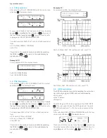
Example 2:
In this example, the external modulation signal is a ”tri-
nary“ code composed of 9 bits. One bit is composed of 2
narrow and / or wide pulses, depending on the combina-
tion expected:
❙A bit composed of 1 wide and 1 narrow pulses is called
OPEN.
❙A bit composed of 2 narrow pulses is called LOW.
❙A bit composed of 2 wide pulses is called HIGH.
For detecting the first bit, a synchronisation bit (long low
level) is present. The modulation frequency is 20 Hz.
CH1: modulation: narrow pulse of 200 µs
wide pulse of 1.8 ms
synchronisation bit of 14 ms
CH2: zoom of CH1
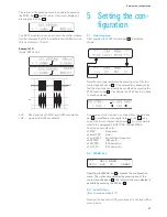
CH1: demodulated signal: DC coupled
CH2: demodulated signal: AC coupled
The return to the modulation menu is possible by pres-
sing the PREV. key
3
and the return to the main display by
pressing the ESC key
13
.
The external modulation input is on the front panel (MOD.
INPUT). The signal can be of any shape, however the AM-
depth and FM/PM deviation programmed is calibrated only
for a 2 V
RMS
signal at the input.
Summary of Contents for HM8134-3
Page 47: ...47 Remote Operation...
Page 50: ...50 Flow Charts Flow Charts Function selection Step control Phi Phi Phi...
Page 51: ...51 Flow Charts Amplitude Modulation Control FSK PSK GATE...
Page 52: ...52 Flow Charts Phase Modulation Control FSK PSK GATE...
Page 53: ...53 Flow Charts Frequency Modulation Control FSK PSK GATE...

