22
Subject to change without notice
C o n t r o l s a n d d i s p l a y
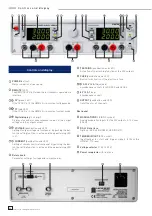
Controls and display
POWER
(button)
Mains connector at rear panel
REMOTE
(LED)
The REMOTE LED is lit when the instrument is operated via
interface.
CV
(green LED)
If the CV LED is lit, the HM8143 is in constant voltage mode.
CC
(red LED)
If the CC LED is lit, the HM8143 is in constant current mode.
Digital display
(2 x 4 digit)
Display of nominal or measurement values of the output
voltage and the output current.
VOLTAGE
(pushbutton and LED)
Setting of output voltage via frontpanel. By pushing the but-
ton the setting function is active and the appertaining LED
is lit.
CURRENT
(pushbutton and LED)
Setting of current limit via frontpanel. By pushing the but-
ton the setting function is active and the appertaining LED
is lit.
Rotary
knob
Parameter setting of voltage and current values.
TRACKING
(pushbutton and LED)
Activation of the tracking function of the 30 V outputs
FUSE
(pushbutton and LED)
Button for activation of the electronic fuse
0-30 V / 2 A
(Adjustable)
4mm banana sockets for SOURCE and SENSE
5 V / 2 A
(Fixed)
4mm banana sockets
OUTPUT
(pushbutton and LED)
On/off key for all channels
Rear panel
MODULATION R / L
(BNC sockets)
Analog modulation inputs for the 30 V outputs, 0-10 V, max.
50 kHz
RS-232 Interface
Options: IEEE-488 (HO880), USB (HO870)
TRIGGER IN/OUT
(BNC socket)
Input/output for start and trigger signals to/from the
HM8143, TTL level
Voltage selector
(115 V / 230 V)
Power receptacle
with line fuse


