24
Subject to change without notice
In order to increase the total available current the outputs of
supplies can be paralleled. The output voltages of the supplies
involved are adjusted as accurately as possible to the same
value. In this mode it is possible that one or more supplies
enter the current limit mode. The output voltage remains in
regulation as long as still at least one supply is in the voltage
control mode. It is recommended but not absolutely necessa-
ry to fi ne adjust the voltages such that the individual current
contributions remain nearly equal. Of course, the maximum
available output current is the sum of the individual supplies‘
maximum currents.
Example:
A load requires 12 V at 2.7 A. Each 30 V output of the HM8143 can
deliver 2 A. First set both channels to 12 V. Then connect both
black and red safety connectors respectively in parallel. The
load is connected to one of the supplies. With the pushbutton
OUTPUT
the voltage will be turned on. It is normal that one
output will current limit at 2 A while the other will contribute
the balance of 0.7 A in voltage regulation.
In case you should parallel power supplies of other
manufacturers with HAMEG supplies make sure
all are specifi ed for this mode of operation. If one
supply of those connected in parallel should have
insuffi cient overload protection it may be destroy-
ed. HAMEG supplies are specifi ed for series and
parallel operation.
Current limit
Current limit means that a maximum current can be set. This is
e.g. useful in order to protect a sensitive test circuit. In case of
an inadvertent short in the test circuit the current will be limited
to the value set which will in most cases prevent damage.
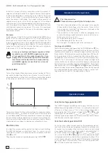
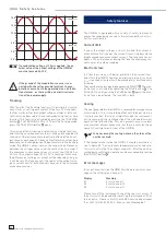
The picture shows that the output voltage V
out
remains stable,
while the current I
out
increases until the current limit selected
I
max
will be reached. At this moment the instrument will change
from constant voltage regulation to constant current regula-
tion. Any further load increase will cause the current to remain
stable while the voltage U
out
decreases ultimately to zero.
Electronic fuse
In order to provide a better protection than current limiting,
the HM8143 features an electronic fuse. As soon as I
max
is
reached all outputs will immediately be disabled (OUTPUT
LED
is off).
They may be turned on again by depressing OUPUT
.
I
out
U
out
U
const
I
max
Adjustment of current
Adjustment
of
volt
age
STOP
STOP
Introduction to the operation
First time operation
Please observe especially the following notes:
– The line voltage indicated on the rear panel corresponds
to the available line voltage, also, the correct fuses for this
line voltage are installed. The fuses are contained in the
line voltage connector housing.
– The connection to the mains is either by plugging into a
socket with safety ground terminal or via an isolation trans-
former of protection class II.
– No visible damage to the instrument.
– No visible damage to the line cord.
– No loose parts fl oating around in the instrument.
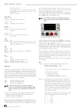
Turning on the HM8143
Turn on the instrument by operating the POWER button
. Du-
ring power up the HM8143 automatically performs a selftest
routine, which checks all of the unit’s important functions and
the contents of the internal memories and registers. While self-
testing is going on, the instrument identifi cation and the versi-
on number of the fi rmware is shown on the two displays (e.g.
HM8143 1.15). The values of the nominal output voltages and
current limits are stored in a non-volatile memory and are read
back after power-on. After turning on the HM8143, the outputs
and the functions TRACKING and FUSE
are deactivated by
default in order to prevent damage being inadvertently caused
to connected loads because the stored voltage or current set-
ting might be too high for the application at hand.
Operation modes
Constant voltage operation (CV)
The HM8143 programmable power supply features various
different operating modes. Of these, it is probably used most
often as a voltage source. This is the normal mode and is
indicated by the CV (constant voltage) LEDs
or
beside
the displays (in this mode V
actual
= V
set
and I
actual
<
I
limit
. Here,
the displayed values represent the measured output voltages
and the measured output current.
Constant current operation (CC)
As soon as the output current reaches the programmed cur-
rent limit value, the power supply automatically switches into
its current source mode, if the electronic fuse is not activated
(see chapter Electronic Fuse). This mode is indicated by the CC
(constant current) LEDs
or
(now I
actual
= I
limit
and V
actual
= V
set
); the CV LEDs
or
extinguish. The measured output
voltage generally drops below the programmed voltage. The
actual measured value can be read off the display. This mode
is only possible if the electronic fuse is not active (FUSE LED
is off) see chapter electronic fuse.
I n t r o d u c t i o n t o t h e o p e r a t i o n


