Subject to change without notice
Measurement of the Shielding
Attenuation of shielded housings
with the E-Field Probe
What are the results if I surround the entire equip-
ment in a shielded housing? This question will be
asked if I fail the CE-Mark EMC test. Unfortunately,
this question can not be answered in general
because a metallic housing is not always a good
shield. No one wants to wait until the next full-
scale EMC test for the results. What if the EUT fails
again? What is needed is a simple measurement
procedure to determine the relative improvement
of the radiated RFI. For this purpose the highly
sensitive E-Field probe is used, which is used as
broad bandwidth measurement antennas to help
answer the above questions.
First, before the E-field probe is used, determi-
nation must be made if the probe has sufficient
sensitivity and bandwidth. In general, all passive
probes are not usable since they have insufficient
sensitivity. The simplest solution to determine the
sensitivity and bandwidth is to measure the exis-
ting ambient field in the practitioner’s laboratory
that is generated by the surrounding transmitters
from 0 to 1,000MHz.
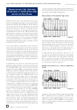
Figure 8 shows the result of such a measurement
which was made with the active E-field probe from
the HZ50/550 probe kit connected to a spectrum
analyzer. From 0 to 50MHz, Figure 8 shows relative
high levels which originate from transmitters
in the broadcast band and shortwave region. In
the frequency range near 100MHz signals from
FM stations are noticeable. Since in the parti-
cular case measured, there were no nearby FM
transmitters, the amplitudes are relatively low.
The strongest signal observed was a UHF TV
transmitter at 7 MHz which was located only
15 km from the laboratory. Then up to 800 MHz
are several weaker (more distant) UHF TV trans-
mitters. The final signals occur above 900MHz
which are related to cellular telephones. This
data shows that the probe is wideband and has
sufficient sensitivity. From the AM band around
1MHz to the cellular telephone band there are
spectrum lines which are significantly above the
noise level. Of course, the spectrum display will
be different at each location depending on the re-
lative distance of transmitters. Even in rural areas
cellular telephone lines must show the absence of
which would show that the probe has insufficient
sensitivity at the higher frequencies.
Measurement of the Ambient Spectrum.
Figure 8
The measurement of the ambient spectrum ser-
ves not only to determine probe sensitivity. If the
measurements are not performed in a shielded
room, the ambient signals can also serve as a
reference to recognize the most important fre-
quencies which do not originate from the EUT.
To perform the measurements, the EUT is set
up, without the additional shield, at a minimum
distance of 0.5 meter from the probe. Then the
EUT is rotated in azimuth to find the maximum of
the radiation from the EUT. At this point the data
is recorded as shown in Figure 9.
EUT RFI Characteristics without Additional
Shield
Figure 9
Comparison of Figure 9 with Figure 8 shows that
RFI is radiated up to a frequency of 1GHz. The
maximum of the radiated power occurs at fre-
quencies between 50 to 50MHz. The strongest
signal is at the marker frequency of 75MHz at a
level of .8 dBm.
Measurement of Shielding Attenuation of Shielded Housings

