Ultra PicoKeyer
27 January 2017 (Firmware V2.2)
Page 15 of 21
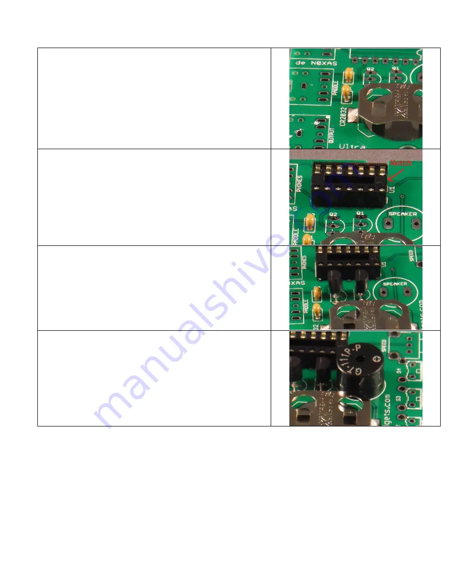
Locate the paper strip with three identical ceramic capacitors in your
kit. These will be small rectangular parts with two parallel leads.
These three are .01 μF (marked 103). Install two capacitors in the
locations shown for C1 and C2. The ceramic capacitors used in your
kit are not polarity sensitive (meaning, don’t worry – you can’t
install them backwards).
Now find the 14-pin IC socket. One end of the socket has a notch to
indicate that it is the “Pin 1” end. Orient the socket so that the
notched end matches the silkscreen markings. Line up and insert the
pins into the PCB. Make sure all the pins go into the holes in the
circuit board. You may need to bend the pins at any two diagonally
opposite corners flat against the bottom of the PCB to hold the
socket in place while you solder. Solder all fourteen pins in place.
Be careful not to use too much heat or too much solder.
Install the two 2N7000 MOSFET transistors in locations Q1 and Q2.
Make sure the flat side of each transistor is facing the direction
indicated by the silkscreen printed outline. Don’t try to push them in
too far. Leave about 1/8” or so between the circuit board and the
bottom of the transistor to avoid putting too much stress on the leads.
Find the speaker and install it in the location marked SPKR. The
speaker is marked with a + on one side. Don’t worry about polarity
as it can be installed either way. Make sure the speaker is inserted
fully into the holes before soldering. Don’t bend the leads of the
speaker; you may want to use a bit of adhesive tape to hold it in
place while you solder it. Don’t spend too much time soldering the
speaker or it may be damaged.


