background image

Hamilton


Home


Products


Canal


Winchester,


OH


76106


61MH0028A


Page


13


SECTION IX: THERMOSTAT WIRING AND 
CONNECTIONS 

Thermostat Wiring


Thermostat wires connect through side of furnace and should 
be no smaller than 24 gauge. Refer to Table 11 for 
recommended wire gauge, lengths and maximum current for 
each wire gauge. 

Maximum 

Wire Length

Thermostat 

Wire Gauge

Thermostat Wire 

Maximum Current

0 - 112 Feet

18

3.0 Amps

0 - 70 Feet

20

3.0 Amps

0 - 30 Feet

22

3.0 Amps


Table 11: Low Voltage Wire Gauge and Max Lengths 


NOTE: 

There is a 3 Amp slow blow bar fuse located in the 

control box that protects the 24 VAC circuit. Replace this fuse 
only with the equivalent 3 Amp fuse.  
Power wires can enter through the side of the unit or through 
the auxiliary entrance, located in the bottom of the unit. 
When bringing wiring through the bottom of the furnace, 
cable connectors must be installed to hold wiring in place and 
to relieve any strain on the wiring.  
These connectors will also serve as a seal between the furnace 
and the floor. Thus, additional sealing is not required. 


The use of a five-conductor cable from the thermostat to the 
furnace is recommended for typical heating or heating/cooling 
installations with a two or three-conductor cable from the 
furnace to the condenser. The thermostat wire colors and the 
typical heating/cooling connections are listed in Tables 12 and 
13.  
A seven-conductor cable from the thermostat to the furnace is 
recommended for a typical heat pump installation with a five-
conductor cable from the furnace to the condenser.  
The thermostat wire colors and the typical heat pump 
heating/cooling connections are listed in Tables 12 and 13. 

NOTE:

 If the thermostat cable is on the left side of the 

furnace move the grommet in the 3/8” hole on the left side of 
the furnace casing to the 3/8” hole on the right side of the 
furnace casing. Run the thermostat wire cable through the 
control box to the low voltage control box. Place the 
thermostat wire next to the low voltage terminal block. Attach 
the strain relief to the control box. Do not attach the strain 
relief to the furnace casing because the sheet metal is too thin. 


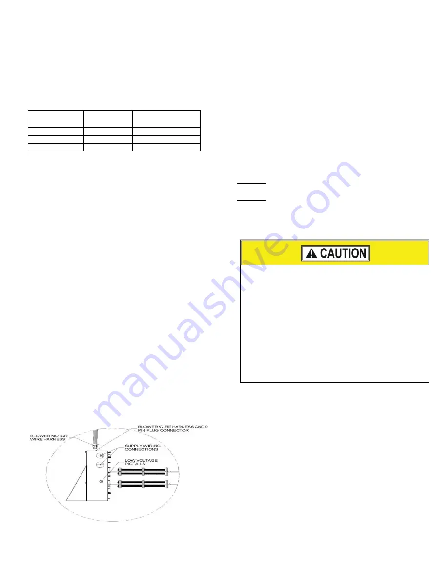
Figure 15: Control Box Power, Low voltage wire 
Locations 

Thermostat Installation 

The thermostat heat anticipator must be-set at 0.7 Amps if the 
thermostat has a manual heat anticipator adjustment. This 
setting should be checked at the time of installation. 


The thermostat may be a “self-setting" type in which case no 
heat anticipator setting will be found on the thermostat, 
eliminating the need for any field adjustment. 
Thermostat should be located on an inside wall in an open area 
to more closely regulate average room air, preferably, where 
there is air movement back to furnace. Locating height of 
thermostat is important. Thermostat should be located 
preferably in a hall way upstream from the furnace return 
airflow, not within three feet of from any windows and 52 to 
66 inches above the floor. 


DO NOT

 place the thermostat within three feet of any of the 

furnace supply air registers 

DO NOT

 place the thermostat within three feet of any of the 

air conditioner supply air registers 


Maintenance, operating and/or programming instructions are 
in the envelope accompanying the thermostat. Give the 
envelope to the home owner. 


Separate Heating and Cooling System; Same Thermostat 

If the furnace and the cooling unit have separate transformers 
be sure to use a thermostat with isolated heating and cooling 
contacts “RC” and “RH” to prevent interconnection of Class II 
24 Volt Systems Refer to Figures 18 and 19. Cycle furnace 
and the air conditioner separately to make sure it will operate 
correctly. 


Most new thermostats have separate heating and cooling 
contacts for use with homes that have a furnace and air 
conditioner that are completely separate and each have a 24 
VAC transformer for system control. These thermostats have a 
“RC” terminal for cooling and a “RH” terminal for heating. 
Connect the cooling unit red wire from the “R” terminal on the 
outdoor unit to the “RC” terminal on the thermostat and the 
RED furnace pigtail wire to the “RH” terminal on the 
thermostat. Refer to Figures 18 and 19 for typical low voltage 
wire connections. 

Do not locate thermostat within three feet of any of the 
following items: 
1


Furnace supply air registers 

2


Cooling unit supply air registers 

3


Lights or heat lamps 

4


Aquariums 

5


Televisions, stereo, amplifiers, surround sound systems 

6


Stoves or any cooking appliance 

7


Refrigerator 

8


Washer and/or dryer 

9


Hot water tank 

10


Sink or near any hot water 

11


Within 15 feet of any electric space heater 

12


Within two feet of any sunlight 

Summary of Contents for WE30 Series

Page 1: ...er Location 11 29 Wiring Diagram 20 kW w C T Blower Motor 22 15 Control Box Power Low Voltage Wire Locations 13 LIST OF TABLES 1 Electric Furnace Model Specifications 2 8 Electrical Data 10 2 Model No...

Page 2: ...Single Stage Heating 30 Table 2 Furnace Model Nomenclature Coil Cabinet Model Front Door of Cabinet Open Top 17 3 4 x 21 3 4 Maximum Air Flow CFM 1 Pleated Air Filter In The Door 2 Pleated Air Filter...

Page 3: ...ce heating cooling equipment Untrained service personnel can perform basic maintenance functions such as cleaning of exterior surfaces and replacing the air filters Observe all precautions in the manu...

Page 4: ...y a closet or alcove must have a certain total free area opening for the return air For A C and HP Furnaces 1 3 HP Blower Minimum 200 in free area opening Use Return Grille or Coil Cabinet For A C and...

Page 5: ...to use SECTION IV SUPPLY AIR AND DUCT CONNECTOR INSTALLATION Duct Connectors 90 DCU0 XX Duct Connectors The duct connector is used to provide a sealed connection between the furnace base and a under...

Page 6: ...the insulation around the perimeter of the duct connector opening 5 Install the floor base over the floor opening with the flanges on the 11 x 13 inch opening facing down Refer to Figures 8 and 9 6 Lo...

Page 7: ...to the floor by drilling two holes through the furnace base and the floor base at the right and left front inside corners of the cabinet Use two screws to secure the furnace to the floor Figure 10 Re...

Page 8: ...e coil cabinet 11 Place the cooling cabinet front door on the unit by inserting the tabs in the bottom of the door into the slots in the coil shelf line up the strike in the front flange of the top co...

Page 9: ...Electrical Code Part I CSA C22 1 and local codes for additional requirements concerning supply circuit wiring Electrical data can be found in Tables 6 7 and 8 IMPORTANT All installation on field wiri...

Page 10: ...er supply will require circuit breaker jumper bar or a jumper wire Refer to the National Electrical Code Table 250 95 for Non Sheathed Conductor Ground Wire Ground conductor must be the same size and...

Page 11: ...le codes Figure 14 Control Box Cover and Circuit Breaker Location Dual Element Box For personal safety be sure to turn the electrical power OFF at the main circuit panel Home Circuit Breaker Box and a...

Page 12: ...cated on the blower housing 6 Follow the instructions in the USERS INFORMATION MANUAL to properly start up the air handler POWER SUPPLY CONNECTIONS If the air handler has been installed prior to insta...

Page 13: ...Installation The thermostat heat anticipator must be set at 0 7 Amps if the thermostat has a manual heat anticipator adjustment This setting should be checked at the time of installation The thermost...

Page 14: ...R Figure 16 Separate Thermostats Separate Air handler and Cooling Unit G R W R G Y Heating Thermostat Cooling Thermostat C Y R G W C COM HEAT COOL Thermostat Interlock Switch Air Handler 24 VAC Transf...

Page 15: ...8 strain relief in the control box and place the thermostat wire cable next to the low voltage terminal block 6 Connect the Red 24 VAC supply thermostat wire to the red pigtail wire and secure the two...

Page 16: ...peratureSwitch W2 J u m p e r Figure 22 Typical Heat Pump 2 Stage Heating Cooling Connections SECTION X MOTOR BLOWER AND FURNACE START UP Selecting the Constant Torque Blower Speed This furnace uses t...

Page 17: ...s to the furnace at the main circuit panel House Circuit Breaker 14 Set the thermostat to the desired temperature Figure 24 Blower Assembly and Blower Deck SECTION XI FINAL SYSTEM CHECKOUT 1 Refer to...

Page 18: ...BLK W H T G R N Y E L L2 B L K WHT B LU B L K BM G R N GGS Y E L C L A S S 2 CLASS 2 CC COMPRESSOR CONTACTOR RVS REVERSING VALVE SOLENOID LEGEND TB TERMINAL BLOCK BMFP 6 PIN MOLEX BLOWER MOTOR PLUG A...

Page 19: ...L1 HC1 T2 L2 G R N GGS C L A S S 2 WHT W H T WHT CLASS 2 CC COMPRESSOR CONTACTOR RVS REVERSING VALVE SOLENOID LEGEND TR TRANSFORMER BMFP 6 PIN MOLEX BLOWER MOTOR PLUG ASSEMBLY GND GROUND CONNECTION B...

Page 20: ...N B R N BRN BLK WHT BLK BLK THERMOSTAT W2 BLK BLK BLK BLK B L K B L K B R N BRN B R N BRN B R N HPM 7 RED ST1 8 BLK L1 9 BLU ST4 Y E L L 2 G R N G N D P R P S T 3 B L K S T 5 B R N 2 4 V C O M BRN G N...

Page 21: ...40 VAC 24 VAC BLK 1 BLK SUPPLY WIRING XMC0 402EBBC Contactor L1 T1 L2 T2 HC1 BLU BLU L1 GND G BLK WHT G R N R E D HC1 HTR1 BLK BLU RED RED T1 C B L1 C irc u it 1 L2 C B C irc u it 1 B L K HC1 T2 L2 1...

Page 22: ...BRN BLU GND BLU PRR ST3 ORN ST2 B R N 2 4 V C O M B L U S T 4 O R N S T 2 P R P S T 3 B L U O R N P U R B L U B L U W H T W B R N BLU B L U B L K B L K R E D R E D FOR A TWO STAGE HEATING THERMOSTAT R...

Reviews: