Design Basics
Installation and Service Manual
Critical Speed of Mainshaft
C.W.F. Hamilton & Co. Ltd. must be consulted when calculating the critical speed of the jet
unit mainshaft.
The heavier splined end of the universal driveshaft should be fitted towards the engine.
If a heavy driveline is used then a transverse vibrational analysis of the jet unit mainshaft should also be
done.
Jet Mainshaft Alignment
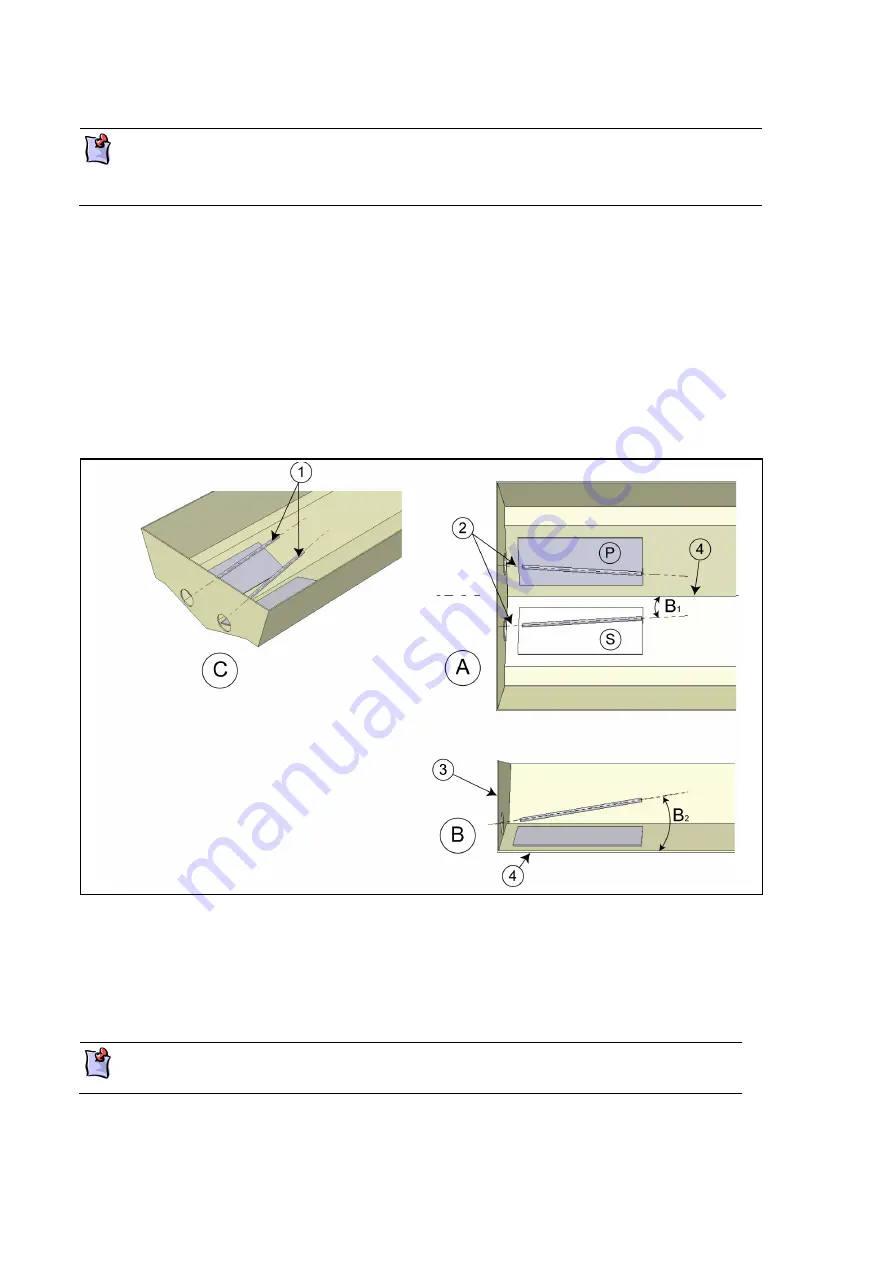
If the jet unit mainshaft is inclined at an angle of 5° to the intake base and the port and starboard jets are
mounted at the hull deadrise angle, then the jet mainshafts are no longer parallel to the keel line in plan.
The following table lists the angle deviation of the jet unit mainshaft when the jet base is mounted parallel to
the keel line.
Figure 9:
Jet Mainshaft Alignment
A
Plan view
3
Transom
B
Section through keel line
4
Keel line
C
Isometric view
P
Port jet
1
Jet unit mainshaft
S
Starboard jet
2
Mainshaft centre line
This diagram applies only to jet units where the mainshaft is inclined at 5° to the intake
base.
3-8
Summary of Contents for HJ212
Page 1: ...HJ212 Installation and Service Manual R3A3 Jet unit Manual ...
Page 20: ...Product Description Installation and Service Manual 2 6 ...
Page 56: ...Commissioning Installation and Service Manual 6 4 ...
Page 62: ...Fault Finding Installation and Service Manual 7 6 ...
Page 82: ...Maintenance Installation and Service Manual 8 20 ...
Page 137: ...Installation and Service Manual Appendix Notes 10 21 ...
Page 141: ...Installation and Service Manual Appendix Notes 10 25 ...
Page 164: ...Appendix Installation and Service Manual 10 48 ...
Page 166: ......
Page 169: ......
Page 171: ......
Page 172: ......
Page 175: ......
Page 176: ......
Page 177: ......
Page 178: ......
Page 181: ......
Page 185: ......
Page 186: ......
Page 188: ......
Page 195: ......
Page 196: ......
Page 197: ...Notes ...


