Overhaul
Installation and Service Manual
Reverse shaft reassembly
Lightly grease the reverse shaft and bushes [8, 9, 10].
Assemble the reverse spacer [28] and washers [31] in the correct order onto the reverse shaft [8].
From inside the vessel, fit the reverse shaft through seal [15] and bush [9]. Continue pushing the reverse
shaft rearwards through bush [10] until the reverse spacer [28] and washer [31] are pushed firmly
against the transom seal ring on the jet unit intake.
From outside the vessel fit flat washer [31] to the end of the reverse shaft [8] protruding from the rear of
the jet unit.
Fit the reverse crank [11] to the reverse shaft and ensure that the reverse crank is fitted with the flat side
of the reverse crank facing rearwards.
Secure the reverse crank to the reverse shaft with cotter [16], special washer [13], spring washer [19]
and nut [17]. Torque load to the recommended torque.
Check for freedom of movement between the reverse shaft and the reverse latch hub.
Reverse link reassembly
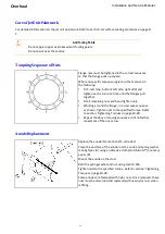
Lightly grease the bores on the link actuator [21].
Apply Loctite 263 to the bolt [25].
Re-assemble the link ball [22], link actuator [21], link o-ring [38] and flat washer [24] onto the bolt [25].
Attach the link actuator [21] to the outside of the port reverse duct arm.
Tighten nut to the specified torque. Refer to section: Tightening Torques on page 10-28.
This is important as the bolt [25] may work loose and fall out, with reverse duct movement.
Reverse duct reassembly
Ensure the thread and surfaces of the reverse duct pivot bolts [4], reverse duct pivots [2] and the reverse
duct pivot bushes [5] are clean.
Coat the reverse duct pivots [2], pivot bushes [5] and washers [3] with a recommended marine grease.
Fit the reverse pivots [2] to the reverse duct arms from inside the reverse duct arms.
Support the reverse duct so that the pivots in the reverse duct are aligned with the threaded holes in the
tailpipe.
Fit washers [3] to the pivot bolts [4] and fit the pivot bolts [4] using Loctite 222 to secure the reverse duct
to the tailpipe.
Tighten the pivot bolts [4] to the recommended torque 95Nm (70lbf ft).
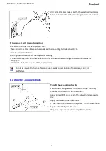
Once the reverse duct is refitted to the jet unit, raise the reverse duct and connect the link actuator [21]
to the reverse crank [11]. Ensure that washers [60] are fitted either side of the head of the reverse crank
[11].
Secure with crank pin [12], washers [60] and split pin [14].
Refit the tension spring [18] to the location point on the starboard side of the jet unit and connect the
free end to the bolt [6] mounted on the starboard upper side of the reverse duct.
Carry out a functional check to ensure the proper operation of the reverse mechanism and adjust the
reverse detent plate [23]. Refer to section: Zero Speed Detent on page 5-12
9-10
Summary of Contents for HJ212
Page 1: ...HJ212 Installation and Service Manual R3A3 Jet unit Manual ...
Page 20: ...Product Description Installation and Service Manual 2 6 ...
Page 56: ...Commissioning Installation and Service Manual 6 4 ...
Page 62: ...Fault Finding Installation and Service Manual 7 6 ...
Page 82: ...Maintenance Installation and Service Manual 8 20 ...
Page 137: ...Installation and Service Manual Appendix Notes 10 21 ...
Page 141: ...Installation and Service Manual Appendix Notes 10 25 ...
Page 164: ...Appendix Installation and Service Manual 10 48 ...
Page 166: ......
Page 169: ......
Page 171: ......
Page 172: ......
Page 175: ......
Page 176: ......
Page 177: ......
Page 178: ......
Page 181: ......
Page 185: ......
Page 186: ......
Page 188: ......
Page 195: ......
Page 196: ......
Page 197: ...Notes ...


