background image

Hamlet Solution Wood & Multifuel Stoves

9

INSTALLATION

GENERAL PRECAUTIONS

Note - All installations must conform to the
appropriate building regulations. 

The Building Regulations for England and Wales
2000 ref Approved Document J 2002 edition
(issued by the DTLR).
The Building Standards (Scotland) (Consolidation)
Regulations.
Detailed recommendations for installation of
appliances, chimneys and flues are outlined in the
current issue of the following British Standards:-
BS6461, BS8303 and BS4543.

Any Manufacturer's Instructions must not be
taken as overriding statutory requirements.

During installation ensure that adequate
precautions are taken to avoid unnecessary risk to
yourself or any householder. In particular the
danger from the caustic nature of the fire cement
should be avoided by using these accepted
methods:

•  Wear gloves when handling fire cement. 
•  Wear goggles when chiselling or looking up   

chimneys.

Make sure that Building Regulations are adhered to
during installation along with any local by-laws. In
the case of heating systems make sure that the pipe
work is correctly bonded to ensure electrical
earthing.

HANDLING

By the time you read this you will appreciate the
weight of the appliance. The Safety and handling
guidelines as set out on page 5 of this manual
should be followed.
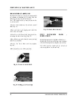
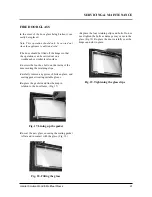
To make movement easier internal fittings, fuel
retainers, grates, firebox liners, flue outlets, hot
plate, throat plate, etc., can be removed. 

Care should be taken to make sure that the hinges
are not damaged during installation.

HEARTH

The stove should be installed to stand on a
constructional hearth of non-combustible materials
not less than 125mm (5'') thick conforming to
Building Regulations. Dimensions of the hearth
should project at least 300mm (12'') forward of the
front of the appliance and 150mm (6'') at the sides.
The surface of the hearth should be free of
combustible materials. In most buildings with solid
concrete floors the requirement will be met by the
floor itself, but mark the perimeter of the hearth to
ensure floor coverings are kept well away or use
different levels to mark the hearth perimeter.

COMBUSTIBLE MATERIALS

A gap of at least 450mm (18'') should be allowed
between the appliance and any combustible
materials including furnishings. Adjacent walls
should be of suitable non-combustible
construction, preferably brickwork. In large
fireplaces take care that any supporting beam is
protected by a 13mm (0.5'') sheet of
Masterboard/Supalux spaced 13mm (0.5'') off the
surface with strips of non-combustible material

- not wood.

Make sure that there is a gap between an
uninsulated flue system and any combustible
material. This gap must be at least 3 x the outside
diameter of the flue pipe, or 1.5 x the flue diameter
to non combustible surfaces. see illustration p13.
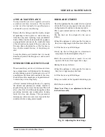
AIR FOR COMBUSTION

There must always be a permanent means of
providing air for combustion into the room in
which the fire is installed. A permanent vent with a
total free area of at least 550mm

2

for every kW

rated output above 5kw should be connected
directly to the outside air or to an adjacent room
which itself has a permanent vent of the same size
direct to the outside air. The fitting of an extractor
fan to either of these rooms is not recommended.

Summary of Contents for Solution

Page 1: ...Wood Multifuel Model Range Operating Installation Manual PLEASE RETAIN THESE INSTRUCTIONS FOR FUTURE REFERENCE Solution 7 Multifuel Rev 3 November 2006 AFS1292 SOLUTION BK054...

Page 2: ...the reliability of our product that we offer a Lifetime Guarantee Should you have any questions about our Solution Stoves that are not covered in this manual please contact the Hamlet dealer in your a...

Page 3: ...Annual Maintenance 21 Summer Storage Non Usage 21 Door Adjustment 21 Dissassemble Airwash 22 Fuel Retaining Bars Inspection 22 Fire Door Glass 23 Service Record 24 OPERATING INSTRUCTIONS Fuel Types 25...

Page 4: ...D IN THIS APPLIANCE TO USE THESE FUELS WILL INVALIDATE THE APPLIANCE GUARANTEE IF IN DOUBT CONTACT THE SOLID FUEL ASSOCIATION TELEPHONE NUMBER 0800 600 000 www solidfuel co uk THE USE OF SPARE PARTS O...

Page 5: ...fire If not properly installed and operated a house fire may result installation must comply with the Building Regulations and conform to all relevant fire safety standards Hamlet Stoves produce a var...

Page 6: ...otplate 6 Rear liner 7 Side liners 2 N A SOL 7 Wood 1 5 2 2 SOL 7 Multifuel N A SOL 5 Wood 1 4 2 7 1 5 2 SOL 9 Wood SOL 9 Multifuel 2 1 4 1 5 1 4 1 5 1 Grate bars 1 1 2 Wood burning tray SOL 11 Multif...

Page 7: ...Instruction Manual 13 Operating tool 1 1 SOL 7 Wood 1 SOL 7 Multifuel SOL 5 Wood 1 1 SOL 9 Wood SOL 9 Multifuel 8 Rear grate bar support 11 Fire door han dle Kool Touch 1 1 1 SOL 11 Multifuel SOL 11...

Page 8: ...1 5 SOL 5 Wood 3 2 1 7 8 4 8 2 2 SOL 9 Wood SOL 9 Multifuel Measured from rear of canopy to the tip of the handle The model and Serial Number of your stove can be found stamped into the casing centra...

Page 9: ...tion HEARTH The stove should be installed to stand on a constructional hearth of non combustible materials not less than 125mm 5 thick conforming to Building Regulations Dimensions of the hearth shoul...

Page 10: ...stove outlet to the outside air To ensure a good up draught it is important that the flue gases are kept warm and that the flue size suits the stove The termination of the outlet at the top of the flu...

Page 11: ...ent J of the Building Regulations for England and Wales is available from The Stationery Book shops and can also be viewed at the ODPM website at www safety odpm gov uk bregs brads htm Details on the...

Page 12: ...12 Hamlet Solution Wood Mutifuel Stoves INSTALLATION Fig 2 A Typical Rear Flue Layout...

Page 13: ...TYPICAL METAL INSULATED CHIMNEY SYSTEM TO BE INSTALLED TO THE CHIMNEY MANUFACTURERS INSTRUCTIONS IN COMPLIANCE WITH BUILDING REGULATIONS AND BS7566 PTS 1 4 A is minimum clearance for non insulated flu...

Page 14: ...or the other rear leg WOOD STOVE VERSION WOOD TRAY The wood burning tray should come fitted in your stove if not please follow these instructions Fully open the fire door and remove the two round fuel...

Page 15: ...e upper bar is fitted in a similar manner but with the end marked L inserted in the rear channel and the end marked H seated on the high section of the comb See fig 8 for the assembled grate layout GR...

Page 16: ...small liner s into the back of the fire Insert side liner panels See Fig 10 Fit the throat plate with the single bend and two cut outs to the front facing up The projecting lugs sit on top of the sid...

Page 17: ...s for individual heating systems should be carried out by a qualified heating engineer In many cases your supplier will be able to offer advice and assistance Direct Systems Stainless steel boilers ei...

Page 18: ...ipe from the expansion tank should be 28mm diameter copper Pipes in unheated spaces must be lagged FINAL CHECK Before handing over the installation to the customer it is strongly recommended that the...

Page 19: ...e calculated natural draught gas appliances only c If clay or concrete flue liners used confirm that they are correctly jointed with socket end uppermost and state jointing materials used d If an exis...

Page 20: ...uch up spray as some paints interact This could ruin the finish and invalidate the guarantee DOOR GLASS The door glass should remain clear during normal daytimeburning Howeverundercertainconditions su...

Page 21: ...w air movement through the stove by opening the airwash and prinmary air inlet s controls to about half way open or leave the door ajar This will allow a free flow of air through the appliance thus pr...

Page 22: ...let Lift outer cover free from body being careful not to damage the ends of each lug Fig 15 Slide off the spacer tube from the centre stud and retain for re assembly Unscrew the inner slider and clean...

Page 23: ...olts on the inside of the door securing the retaining clips Carefully remove any pieces of broken glass and sealing gasket wearing suitable gloves Re place the gaskets and line them up in relation to...

Page 24: ...our Solution Stove that is not covered in this manual please contact your Hamlet Stoves retailer Please keep all repair receipts safely Please ensure you have this manual available when an engineer vi...

Page 25: ...hurnacite Plus Centurion Maxibrite Extracite Pureheat Blazebrite Taybrite Sunbrite Doubles Singles Anthracite Large Nuts and Welsh Dry Steam Coal Large Small Nuts Approval does not cover the use of ot...

Page 26: ...r long periods consequently more care in setting the controls and some familiarisation is necessary when burning anthracite Use the smallest size fuel Stovesse or Small Nuts Proceed as for manufacture...

Page 27: ...s housed in a cover plate and is located above the fire door Sliding the control knob to the right as far as it will go achieves the fully open position Sliding it to the left will shut off the air in...

Page 28: ...de ashing is complete re set grate to previous position Empty the ash pan Note Do not force the riddling lever TO EMPTY THE ASH PAN Open the fire doors Fit the fork end of the operat ing tool into th...

Page 29: ...draught is not present in the chimney Fire door is closed If the fire goes out with unburnt fuel left in the firebox increase the air opening slightly and vice versa In the morning Open the air contro...

Page 30: ...erosol Paint Gothic Tracery SOL 11 Multifuel SOL 11 Wood Lattice Tracery AFS 101a AFS 101a AFS 101a AFS 101a AFS 101a AFS 101a AFS 101a AFS 101a AIB 0 AIB 0 AIB 8 AIB 8 AIB 9 AIB 9 AIB 10 AIB 10 Stove...

Page 31: ...2 Wood burning tray SOL 11 Multifuel SOL 11 Wood 3 Throat plate N A N A AFS 1197 AFS 1286 AFS 1286 AFS 1287 AFS 1287 AFS 009a AFS 009a AFS 010 AFS 010 AFGS 064 AFGS 064 AFS 009 AFS 009 AFS 1207 AFS 1...

Page 32: ...AFS 008 AFS 008 AFS 008 AFS 1214 AFS 1214 AFS 1215 AFS 1215 AFS 1010 AFS 1010 AFS 1010 AFS 1010 AFS 047 AFS 047 AFS 047 AFS 047 AFS 1205 AFS 1208 AFS 1208 AFS 058 AFS 058 AFS 051 AFS 051 12 Replaceme...

Page 33: ...ire Door Rope Kit Complete With Glue AFS 1021 SOL 11 Multifuel SOL 11 Wood AFS 1294 AFS 1294 AFS 1295 AFS 1295 AFS 1222 AFS 1222 AFS 1222 AFS 1222 AFS 1292 AFS 1292 AFS 1292 AFS 1292 N A AFS 1226 N A...

Page 34: ...final If your appliance proves to be defective as a result of faulty materials or workmanship during the guarantee period we will repair or replace it FREE OF CHARGE as long as the fire has been inst...

Page 35: ...any other costs including labour incurred in its replacement Documentation must be retained and produced in the event of a warranty claim This guarantee specifically does not cover accidental damage m...

Page 36: ...BARS WOODBURNING TRAY FIREBOX LININGS THROAT PLATE AIR WASH DOOR CATCH KOOL TOUCH HANDLE ASH PAN ADJUSTING FEET X 2 OPERATING TOOL CONVECTOR KIT FIXINGS X 4 OPERATING INSTRUCTIONS Model Serial No I ve...

Reviews: