background image

FREE 

DOWNLOAD 


COURTESY  

OF 

N9SOR 


WWW.HAMMARLUND.ORG

Summary of Contents for HQ-180 Series

Page 1: ...NICAL D SCRI ION I AND OP RATING t INSTRUCTIONS HAMMARLUND MANUFACTURING COMPANY INC A Giannini Scientific Co 73 88 Hammarlund Drive Mara Hill North Carolina Export Department 13 Eaat 40th Street New...

Page 2: ...his group will include all direct correspondence with the customer and with warra nty repair stations jobbers and representatives It will also include factory repair facilities As you can see this is...

Page 3: ...THE HQ 180 AND 180 A SERIES OF COMMUNICATIONS RECEIVERS FREE DOWNLOAD COURTESY OF N9SOR WWW HAMMARLUND ORG...

Page 4: ...ion Service and Maintenance Removing and Replacing The Chassis Removing and Replacing The Front Panel Alignment Procedure Tube Socket Voltages Tube Socket Resistances Parts List Schematic Diagram Page...

Page 5: ...s compensation for loading effects ot various type antennas or balanced trans mission line Beat Frequency Oscillator Variable from zero beat plus minus 2 kcs plus fixed position for SSB Slot Filter Ra...

Page 6: ...Q multi plier or converter System socket for simplified associated transmitter receiver control S meter controls Antenna input terminals plus S0239 Dimensions 10 1 2 H x 19 W x 13 D Wt 381bs Shipping...

Page 7: ...ity and easy tuning of the desired signal AVC An extremely fast attack delayed AVe circuit is employed A four position cont col on the front panel permits the selection of OFF AVC or SLOW MEDIUM FAST...

Page 8: ...kc divs 1 05 to 2 05 me cal in 10 kc divs 2 05 to 4 04 me cal in 20 kc divs 4 0 to 7 85 me cal in 50 kc divs 7 85 to 15 35 Inc cal in 100 kc divs 15 35 to 30 0 me cal in 100 kc divs BAND SPREAD TUNING...

Page 9: ...but useable with other transmitters as well This is part PL39286 G1 at 8 50 4 A new three 3 position BFO switch is provided enabling the BFO to be in the off position SSB where the BFO is fixed for o...

Page 10: ...ion is to turn the band switch to the required position and tune the main dial to the ap proximate frequency rocking the knob finally for maximum S meter indicatiLm In order to ensure proper operation...

Page 11: ...ciated transmitter Wh n using an outside antenna it is always best to install a lightning arrestor Such a device drains off the atmospheric charge in a safe manner pr tecting you and the Receiver Note...

Page 12: ...e phones are deliberately mismatched to reduce the level into them If more level or volume is desirable low impedance phones may be employed These may be any of the popular imperiances such as 8 16 or...

Page 13: ...ion and installation Either a single wire or a balanced antenna may be used with the HQ 180A The front panel antenna trimmer control is designed to permit a good match to almost all antenna systems of...

Page 14: ...NGLE WIRE ANTENNA 1 2 WAVE 50 OHM COAXIAL CABLE 1 2 WAVE LEN61H 468 FREQ MCS l6 COAX PLUG DIPOLE 75 OHM TWIN LEAD USE 300 OHM TWIN LEAD FOR FOLDED DIPOLE LUGS ANTENNA FREE DOWNLOAD COURTESY OF N9SOR W...

Page 15: ...who have never oldered it is recommended that some practice be obtained before attaching a plug to a shielded cable However the experience gained from work on even one hi fit kit or Joadio is ample f...

Page 16: ...NNA COAXIAL CABLE TWIN LEAD FOR 50 OHM FOR DIPOLE ANTENNA ANTENNA CONNECTION TO GOOD EXTERNAL GROUND NOTE WHEN COAX IS USED LINK MUST BE CLOSED BETWEEN A a G THIS LINK IS ONLY OPEN WHEN TWIN LEAD OR B...

Page 17: ...DUCTOR TIN EXPOSED CENTER CONDUCTOR 8 SCREW PLUG SUB ASSEMBLY ON ADAPTER SOLDER BRAID TO JI jm Cl SHELL THROUGH SOLDER HOLES USE ENOUGH HEAT TO CREATE BOND OF BRAID TO SHELL SOLDER CONDUCTOR TO CONTAC...

Page 18: ...PIN END OF PLUG SWITCHED 6 3 VAC FOR FIL L _ GROUND ACCESSORY SOCKET CONNECTIONS The system socket connections provide for a variety of uses depending upon the transmitter system installed Compatibil...

Page 19: ...s often extended to many times normal because it is not subjected to the hardships of physical expansion and contraction due to heating and cooling when power is applied and removed If the receiver is...

Page 20: ...meter accuracy also that the high frequency markers mentioned above are approximate settings of the main dial to be used in setting up the amateur scales of the band spread dial Set the band spread di...

Page 21: ...s an extremely sharp adjustable slot or hole tn the selectivity curve It is normally located outside of the passband of the second IF 455kc s It is brought into the passband for the pur ose of elimina...

Page 22: ...R CONNECTIONS SET TO SEND TO USE CALIBRATE CRYSTAL SEE CODE RECEPTION INSTRUCTIONS MAIN TUNING KNOB SET TO DESIRED VOLUME BAND SELECTOR KNOB DIAL CALIBRATION TO BE USED WITH CALIBRATION CRYSTAL SEE CO...

Page 23: ...E NOTE 2 CODE RECEPTION BAND SELECTOR KNOB TUN FOR MAX SIGNAL LEVEL r o SEE NOTE 4 HEADPHONES SET TO RECEIVE IF RECE IVER IS USED ALONE IF RECEIVER IS TO BE MUTED BY TRANSMITTER RELAY CONTACTS REAR CO...

Page 24: ...ed tone 7 On SSB carrier level meter fluctuates with audio Tune for maxi mum audio or apparent S meter level 8 SSB Single Side Band signals can be identified by the lack of a carrier or beat note whis...

Page 25: ...HEADPHONES SET TO RECEIVE IFRECEIVER IS USED ALONE IF RECEIVER IS TO BE MUTED BY TRANSMITTER RELAY CONTACTS REAR CON NECTIONS SET TO SEND TO USE CALIBRATE CRYSTAL SEE CODE RECEPTION INSTRUCTIONS MAIN...

Page 26: ...chematic diagrams one will illustrate the overall system while the other will provide all of the connection details The X series of receivers provides an eleven position fixed frequency crystal oscill...

Page 27: ...0KC XTAL CAL 6C4 OSC VFO J IN A SERIES HQ 180 a HQ 80A SERIES RECEIVERS 455KC 455KC 60KC 60KC IF AMP 455KC AMP SLOT 2nd IF IF AVC AM NOISE GATE IF FILTER CONV AMP AMP DETECTOR LIMITER RECTIFIER 395KC...

Page 28: ...es tube bias permitting increased amplification and thereby increasing sensitivity to weaker signals From the RF amplifier the signal is applied to the first mixer where it is heterodyned with the out...

Page 29: ...is passed through the slot circuit This circuit is designed to provide a narrow section of fre quency rejection capable of being set precisely on an interfering signal The slot depth control permits i...

Page 30: ...IIV f I ot I I I I When Sidebands Sw I is set to Lower a mirror image of the Upper Sideband I I I appears in the 9 V Lower Sideband I I I I I 1 I I I Selectivity Sw Sidebands Sw E I KCS UPPER F 2 KCS...

Page 31: ...is exactly the same as for CW except that the BFO is a fixed frequency in the IIAn series For the HQ 180 series keep BFO con trol at 11011 In SSB operation tuning for intelligibility requires that the...

Page 32: ...42 R74 CI2S r CI24 CI61 R40 C44 X s I I I I DETECTOR BFO a NOISE LIMITER CIRCUITS AM MODE SWITCH SSSo b POSITIONS CWO S7 C42 La FROM 1 I 60 KCS I F 6 V8C AM DETECTOR C43 V9 2 PRODUCT DETECTOR R37 BFO...

Page 33: ...gnal of known strength is applied to the receiver usually from a pre cise signal generator whose output level can accurately be measured The audio stages are conventional in nature except for the spec...

Page 34: ...6 R93 IN OFF ONLY veB DETECTOR FOR AVC AVC SWITCH POSITIONS o SLOW S8 OFF oMEDIUM o FAST 8 R21 I VI3B METER AMP ________ l 2 0 R88 R91 R84 R85 R83 R22 l CI31 R 99 5 DELAYED AVC TO Ave TO 2 NO IF AMP R...

Page 35: ...oved muting the receiver Further or alternate muting can be applied through the system socket from the transmitter in the A series only 4 2 0 2 w 4 J u 6 u 8 0 0 0 10 12 0 it 14 0 0 16 18 20 22 I _ i...

Page 36: ...NES IT29 I r 1 II AUTO RESPONSE FEEDBACK R80 LOOP AUDIO 1 V15 J V16 1 I01500 n AF I I GAIN I r 6 7 1 3 211 R79 I I 17 1 2 R77 GND AUTO RESPONSE CI RCUIT FREE DOWNLOAD COURTESY OF N9SOR WWW HAMMARLUND...

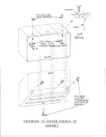
Page 37: ...gnment it will be necessary to take the chassis out to gain access to the under chassis alignment settings Further disassembly is not recommended except in the case of dial cord replacement As this is...

Page 38: ...FREE DOWNLOAD COURTESY OF N9SOR WWW HAMMARLUND ORG...

Page 39: ...nel from the Chassis Refer to the diagrams for the locations and identification of all parts Step 1 Remove all knobs except those of the clock and dial calibration Turn all capacitors so that their pl...

Page 40: ...OTHERS ROUND WITH WHITE MARKS DIAL CALI BRATI ON KNOB POINTER SHAPE LARGE ROUND sk LARGE ROUND POINTER SHAPE REMOVE ALL KNOBS EXCEPT CLOCK AND DIAL CALIBRATION STEP 1 FREE DOWNLOAD COURTESY OF N9SOR...

Page 41: ...AND WASH ERS INDICATED SET SCREW OF KNOBS TO LINE UP WITH FLATS OF SHAFTS PRY OFF TWO SCREWS AND POINTERS LOCK WASHERS CAUTION TO PREVENT DAMAGE TO CAPACITOR PLATES MAKE SURE THEY ARE FULLY MESHED STE...

Page 42: ...J DETAIL OF DIAL CALIBRATION DRI VE J II I BlK 8 WHT I RED 8 BLK CLOCK WIRES I UNSOLDER I I I IREAR OF PANEL L RED 8 BLK BlK 8 WHT s METER WIRES UNSOLDER REMOVE AND UNSOLDER AS INDICATED FOR CONVENIE...

Page 43: ...IVE LOCKWASHER PHILLIPS SCREW AND NUT WITH CAPTIVE LOCKWASHER PHILLIPS SCREW AND ilL BRACKET REMOVE SCREWS NUTS AND BRACKET INDICATED ICAUTION HOLD PANEL TO PREVENT FALLING I STEP 4 FREE DOWNLOAD COUR...

Page 44: ...en turn the dials so that the left end of each dial is approximately vertical Push on the dials so that the shaft ends are about 1 8 inch cecessed It should be possible to see the previous set screw m...

Page 45: ...tep 1 illustration Step 11 This step is for dial alignment Reconnect the Receiver and turn it on Allow it to warm up for about a half hour After the warm up period tU11e in to 4 MCS on the Main Tuning...

Page 46: ...LOCKWASHER AND NUT LOCKWASHER ONLY BAND SPREAD FRONT OF DRIVE CHASSIS HARDWARE FOR MOUNTING CONTROLS WHEN PANEL IS REMOVED STEP 7 FREE DOWNLOAD COURTESY OF N9SOR WWW HAMMARLUND ORG...

Page 47: ...LS COUNTER CLOCKWISE SWITCH OFF IF SO EQUI PPED SET CAPACITOR PLATES IN MESH PUSH ON POINTER THEN KNOB KNOB ALIGNMENT POSITIONS REMAINING SHAFTS HAVE FLATS IF KNOB ALIGNMENT IS REQUIRED REPLACING POIN...

Page 48: ...transformer down nearest the table top This is to permit access to both the top and bottom of the chassis Before operating the Receiver adjust the 11 S1I meter pointer screw on the front face of the m...

Page 49: ...actually turning the proper slug it is some tIme s easy to be adjusting the wrong one or even to be turning both at once 1f they happen to be close together inside the coil IF ALIGN NIENT Step 1 Conne...

Page 50: ...RATION TO CENTER MARK AM CENTER 0 5 KCS UPPER TO BE ADJUSTED 100 ON AS INSTRUCTED LOG SCALE SET PLATES TO SET TO 7 85 15 35 MCS 1 2 MESH BAND INITIALLY CONTROL SETTING AT START OF ALIGNMENT FREE DOWNL...

Page 51: ...and adjust the top and bottom cores of 1 3 1 4 and 1 5 for maximum negative reading of the VTVM Remember to reduce the IF input signal level as necessary to maintain about 5 volts This completes the I...

Page 52: ...ight and should be well within this range from the low frequency to the high freqllency adjustments Check and if the pointer is at the either end of this range reset it as required and Adjust T12 as f...

Page 53: ...no further improvement can be noted Finish with the high frequency adjustments Band Switch to 7 85 15 35 mc s Generator and dial to 7 85 mc s Adjust T26 Top of T21 and T 16 for maximum negative readin...

Page 54: ...R20 rear of chassis to zero 5 The meter sensitivity adjustment R19 is set to obtain an S9 reading with 50 microvolts input with the RF gain control at max NOTE Usually RIg will not require readjustmen...

Page 55: ...0 7 85 60 15 7 1 1 2 1 RF COIL ADJUSTMENTS COIL FREQ LOCATION MCS T21 TOP 7 9 BOT 15 7 TOP I 2 1 T20 BOT 4 0 TI9 TOP I 60 BOT 1 1 TOP ONLY HF OSC COIL ADJUSTMENTS MCS T27 115 7 T26 I 7 9 T25 I 4 0 T24...

Page 56: ...RF TRIMMER ADJUSTMENTS MCS C57 I C58 C55 C56 C53 I C54 15 0 I 30 0 4 0 7 8 1 0 I 2 0 C79 3035 KCS T5 455 KCS __ 14 455 KCS T3 455 KCS FREE DOWNLOAD COURTESY OF N9SOR WWW HAMMARLUND ORG...

Page 57: ...IFQ 6BA6 DO AVC AM OET va 6Bve l 0 D D IS V _ DMIXER lc D 455KC e 0 06BE6 6C4 D IF V4 6BA6 v J V DO DOD D Q2ndCONV 6BE6 e REG OA2 f LI M 9I6ALS 1st AF QDELAYED AVC 6AV6 POWER OUTPUT 6AQ5 o METER ADJ e...

Page 58: ...4 6Al5 D D 1st AF I SDELAYED AVC DDD 6AV6 8RFAMPL 6BZ6 POWER VI7 OUTPUT 6AQ5 ODD 3 ODD 0 REG OA2 60KC BFO IF V7 METER SBA6 12AU7 CAL RECT DO PROD 6BZ6 5U4 GB DET 50 60 12AU7 115V 230V AVC AM DET va D...

Page 59: ...VAC FROM PIN END OF PLUG FROM RECEIVER ALWAYS ON IF RECEIVER 3 2n L 500l SPEAKER OR PLUGGED INTO LIVE POWER L GND LINE CONN SYSTEM SOCKET CONNECTIONS t RFAMPL 68Z6 DO DDD 60 KC t IF 6BA6 DDD DO 60KC t...

Page 60: ...F V7 6BA6 OD AVC AM OET 6BV8 GGATE v y 6BA6 DtV3 Ist CONV 6BE6 455KC t D IF 6BA6 DD O 5 2nd CONY 6BE6 REG OA2 50 60 1 115V 230V L1M v J 6AL5 1st AF Vi5 DELAYED AVC 6AV6 Q POWER OUTPUT 6AQ5 o ACCESS SO...

Page 61: ...2 IlEG V6 IF AIII 6BA6 1 47 MEG 0 0 19K 61K 68 V7 IF AMP 6BA6 470K 0 0 20K 60K 68 V8 DET AVC 6BV8 560 17 30K 0 47K 70 0 4 7K V9 PROD DET 12AU7 INF 20K S8B 470K 820 55K lOOK 820 0 V10 LIMITER 6AL5 210...

Page 62: ...0 0 6 3 AC 0 240 83 1 0 V7 IF AIIP 6BA6 0 0 6 3 AC 0 230 82 1 0 V8 DET AVC 6BV8 5 0 235 0 24 0 0 4 V9 PROD DET 12AU7 220 58 0 7 0 888 6 3 AG 6 3 AC 100 888 0 7 0 888 0 VIO LIMITER 6ALS 3f i OFF 24 MAX...

Page 63: ...EG o o 19K 61K 68 BA6 I I I I I I I I I I IP t I 470K o 20K 60K 68 6BA6 DET AVC V8 17 47K 70 o 560 30K o 4 7K 6BV8 PROD DET INF 55K lOOK 820 V9 470K 820 o 20K SSB LIMITER 12AU7 1 5 MEG 1 4 MEG yIO 220...

Page 64: ...BA6 0 0 6 3 AC 0 240 s 1 0 V7 IF AMP 6BA6 0 0 6 3 AC 0 230 82 1 0 V8 DET AVC 6BV8 5 0 235 0 24 0 0 4 V9 PROD DET 12AU7 220 88B 0 7 0 88B 6 3 AC 6 3 AC 100 888 0 7 G 88B 0 VI0 LIMITER 6AL5 36 OFF 24 MA...

Page 65: ...Reg 150 14 OA2 V AF f VC 15 6AV6 V Power Amp 0 16 6AQ5 V IF Gate 0 l7 6BA6 Systems 0 Socket Ace Socket 2 1 5 RF 5 8 min 1 35 2 0 0 0 0 0 0 30 Offl o max 9 0 cal 0 1 3 13 0 A V C 0 SOCKET PIN NUMBERS...

Page 66: ...MEG V 6 IF Amp 6BA6 1 47 MEG 0 0 19K 61K 68 V 7 IF Amp 6BA6 470K 0 0 20K 60K 68 V 8 Det AVC 6BV8 560 17 30K 0 47K 70 0 4 7K V 9 Prod Det 12AU7 INF 20K SSB 470K 820 55K lOOK 820 0 V 10 Limiter 6AL5 210...

Page 67: ...0 24 0 0 4 8 6BV8 V Prod Det 220 SSB 0 7 0 SSB 6 3 AC 6 3 AC 100 SSB 0 7 0 SSB 0 9 12AU7 V Limiter 36 off 30 iOffl 0 6 3 AC 36 IOf 0 30 l f j 10 6AL5 24 max o max 24 max o max V Cal 60 cal 9 0 cal 6...

Page 68: ...19K 61K 68 V 7 IF f mp 6BA6 470K 0 0 20K 60K 68 v 8 Det 6BV8 Ave 560 17 30K 0 47K 70 0 4 7K 9 Pro0 Det 12A U7 INF 20K SSB 470K 820 S5K j OOK 820 0 V 10 Limiter 6ALS 210K 1 4 MEG 200K LIM ON 0 220K 0...

Page 69: ...C26 Variable Slot Tuning K4204l l C28 C104 C110 C115 Fixed Silver Dur Mica DM l5 7 mmi 500 W V D C K23006 24 C1l7 C122 C29 Fixed Silver Dur Mica DM 15 780 mmi 500 W V D C K23006 39 C30 C63 C64 C78 C1...

Page 70: ...500 W V D C Fixed Silver Dur Mica DM 15 14 mmf 500 W V D C Fixed Silver Dur Mica DM 15 21 mmf 500 W V D C Fixed Silver Dur Mica DM 15 16 mmi 500 W V D C Fixed Silver Dur Mica DM 15 47 mmf 500 W V D C...

Page 71: ...w 10 R22 820 ohms 1 2 w 5 R23 R44 1 megohm 1 2 w 10 R24 120 ohms 1 2 w 5 R25 S9 ohms 1 2 w 5 R26 Variable 200 ohms slot depth R28 R4S R45 220K ohms 1 2 w 10 R48 R68 R71 R30 RS2 R37 R40 R76 470K ohms...

Page 72: ...Assembly AC ON OFF Part of R6 and R15 Send Receive Calibrate Selectivity Sideband AM SSB CW AVC TRANSFORMERS Transformer Mixer Plate 3035 and 455 KC IF Transformer Crystal Grid IF Transformer 355 Kcs...

Page 73: ...Model MISCE LLANEOUS Fuse holder Fuse 3 Amp type 3 AGC Lamp pilot No 47 6 3 V 15A External Relay Rec8ptacle Phone Jack Antenna Connector SO 239 OPTIONAL ACCESSORIES Telechron Clock Assembly Conversion...

Page 74: ...sory SQJcket HF Oscillator Switch Assem Switch AM SSB CW Power Transformer Filament Transformer Output Transformer Capacitor Fixed Dur Mica DM 15 47 mmf 300V ADDENDA TO PARTS LIST FOR HQ 180AX DESCRIP...

Page 75: ...INDICATES PRE tL SENT CONNECnON REMOVE WHEN INSTALLING CLOCK WIRES J J1o JI t j BLACK WHITE l L __ l Sl YELLOW BLACK I R F I I I I I I L __ RED BLACK Ii ON OF I I CLOCK INSTALLATION HQ 170 a HQ 180 1...

Page 76: ...ION REMOVE WHEN INSTALUNG CLOCK WIRES BLACK WHrTE I __ __ JD t YE LLOW BLACK I I I I I I I I I L__ R F 8 ON OFF 4 J A C liNE NOTE THE 4400 1 RESISTOR MUST BE JUMPED OR SHO T CIRCUITED FOR 115 117 VOLT...

Page 77: ...THE HX 50 TRANSMITTER a DISCONNECT GRID BLOCK BIAS GREEN LEAD FROM PIN S OF TBIOI PIN NO 1 OF THE HQ ISOA OR HQ BOAX RECEIVERS SYSTEM b WIRE ORANGE LEAD TO PIN 7 AND YELLOW LEAD TO PIN 6 SOCKET SHOULD...

Page 78: ...J CIS4 CtlS L2 C28 1l 7 2 120 C22 Ot UF AI rl 10 C27 l 0IUF L 10 j C C2 I r OIUF I C29 I I 780 U 5 I I _J L __ _ _ L ADAPTER 8L1 BLK YEL BLK GRN BLK R O FREE DOWNLOAD COURTESY OF N9SOR WWW HAMMARLUND...

Page 79: ...I 0110 vII V4 va v Cl2C r40UF 350V I e 7 DIAl L I II 11 4 4 0 J j J 1 D D 4 l 4 4 4 r t 4 4 4 Cl51 OIU R O 22 0 0 100 i ILK to C21 I T C I OIU 1400Y I SCHEMATIC DIAGRAM HQ 180A I FREE DOWNLOAD COURTE...

Page 80: ...CI 3 C2 1t 2 120t e22 2 R26 01 UF 10 1 39 200 I k 0 Of FREE DOWNLOAD COURTESY OF N9SOR WWW HAMMARLUND ORG...

Page 81: ...po III v V vo YO V VI VIO VII 113 VI no vzo o l 0 0 i elf Ct56 I i 1 80 21 w i KC L _J SCHEMATIC DIAGRAM HQ 180AX FREE DOWNLOAD COURTESY OF N9SOR WWW HAMMARLUND ORG...

Page 82: ...CII CI 4 ellS _ _ L _ _ L __ 4 _ J e22 01 UF 10 2 120 R25 R26 I I I J SLOT FREQ FREE DOWNLOAD COURTESY OF N9SOR WWW HAMMARLUND ORG...

Page 83: ...RIO 3 4 IW V16 IVl7 VII 3 3 3 Rloe ZZn IW SCHEMATIC DIAGRAM HQ 180 FREE DOWNLOAD COURTESY OF N9SOR WWW HAMMARLUND ORG...

Page 84: ...511 TI II j jlr l I Q 1 QC 4 h I I I 24 120 r __ Tt_ I I I I I L 11 ClS4 C155 FREE DOWNLOAD COURTESY OF N9SOR WWW HAMMARLUND ORG...

Page 85: ...e 10 4 t t lZA SCHEMATIC DIAGRAM HQ 180XE FREE DOWNLOAD COURTESY OF N9SOR WWW HAMMARLUND ORG...

Page 86: ...Company be liable for damages by reason of the failure of the equipment to function properly or for any consequential damages This Warranty is valid for the original owner of the equipment and is con...

Page 87: ...ESTABLISHED 1910 Printed in U S A FREE DOWNLOAD COURTESY OF N9SOR WWW HAMMARLUND ORG...

Reviews: