background image

Bandsaw

N4400

Table of contents

Table of Contents

1 General .......................................................................................................... 5

1.1 Explanations of the symbols .............................................................................................5
1.2 Information regarding the manual ....................................................................................5
1.3 Liability and warranty .....................................................................................................6
1.4 Copyright ......................................................................................................................6
1.6 Spare parts ...................................................................................................................6
1.7 Disposal ........................................................................................................................7

2 Safety ............................................................................................................ 8

2.1 Intended use ..................................................................................................................8
2.2 Manual contents ............................................................................................................8
2.3 Making changes and modifications to the machine.............................................................8
2.4 Responsibilities of the operator .........................................................................................9
2.5 What is required of the personnel ....................................................................................9
2.6 Work safety ..................................................................................................................9
2.7 Personal safety .............................................................................................................10
2.8 Hazards arising from the machine ..................................................................................10
2.9 Other risks ..................................................................................................................10

3 Declaration of Conformity ............................................................................. 11
4 Technical data .............................................................................................. 12

4.1 Dimensions and weight .................................................................................................12
4.2 Operation and storage conditions ..................................................................................12
4.3 Electrical connection .....................................................................................................12
4.4 Noise emissions ...........................................................................................................13
4.5 Dust extraction .............................................................................................................14

5. Setting up the machine ................................................................................. 15

5.1 Overview ....................................................................................................................15
5.2 Data plate ...................................................................................................................16

6 Setup and installation ................................................................................... 17

6.1 Safety instructions ........................................................................................................17
6.2 Positioning ..................................................................................................................17

6.2.1 Safety instructions ...................................................................................................18
6.2.2 Setting up the work table .........................................................................................18

7 Operation .................................................................................................... 19

7.1 Safety instructions ........................................................................................................19
7.2 Switching on the machine .............................................................................................20
7.3 Authorised work techniques ...........................................................................................20
7.4 Authorised work techniques ...........................................................................................21

7.4.1 Positioning the 90° end stop on the work table ...........................................................21
7.4.2 Parallel cutting fence ................................................................................................21
7.4.3 Saw blade replacement/tension ................................................................................22
7.4.4 Longitudinal cut along the marked line .......................................................................22
7.4.5 Cutting round work-pieces in the transverse direction ...................................................23
7.4.6 Longitudinal cut of narrow or thin work-pieces with the guide fence ...............................23

3

Summary of Contents for N4400

Page 1: ...Keep this manual handy and in good condition for continual reference User Manual Bandsaw N4400 Dok ID 503 15 4502 Englisch 2010 10 01 Translation...

Page 2: ...o personnel when they are using maintaining or repairing the machine Attention Upon arrival the machine must be inspected immediately If the machine was damaged during transport or if parts are missin...

Page 3: ...12 4 2 Operation and storage conditions 12 4 3 Electrical connection 12 4 4 Noise emissions 13 4 5 Dust extraction 14 5 Setting up the machine 15 5 1 Overview 15 5 2 Data plate 16 6 Setup and installa...

Page 4: ...uide 26 8 Maintenance 27 8 1 Safety instructions 27 8 2 Cleaning and lubrication 27 8 3 Drive belts 28 8 3 1 Adjusting the belt tension 28 9 Faults 29 9 1 Safety instructions 29 9 2 What to do in case...

Page 5: ...Warning Danger electric current This symbol warns of potentially dangerous situations related to electric current Not observing the safety instructions increases the risk of serious injury or death Re...

Page 6: ...It is desig nated solely for those persons who work on or with the machine All descriptions texts drawings photos and other depictions are protected by copyright and other commercial laws Illegal use...

Page 7: ...be separated without any problem This material is also easy to dispose of and does not pollute the environment Attention Used electrical materials electronic components lubricants and other auxiliary...

Page 8: ...improper use that are made against the manufacturer and its authorized representatives shall be rejected The operator shall be solely liable for any damage that results from improper use of the machin...

Page 9: ...nd recognise potential risks If the personnel lack the necessary knowledge for work ing on or with the machine they must first be trained Responsibility for working with the machine installation servi...

Page 10: ...s of this analysis and correspond to state of the art technology The machine is considered operationally safe when used properly Nevertheless there are some residual risks that must be considered The...

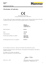
Page 11: ...ertificate No HO 081076 EG Declaration of Conformity according to Machine Guidelines 2006 42 EG We hereby declare that the machine indicated below which corresponds to the design and construction of t...

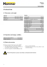
Page 12: ...nst dam ages e g armoured conduit Connected vacuum hoses have to be earthed to avoid electrostatic charges Attention All operations may only be executed by an authorised electrical technician Maschine...

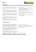
Page 13: ...sion levels it is not possible to state whether increased safety measures are required Factors which can considerably influence the present immission level at the workplace include the duration of exp...

Page 14: ...a mini mum of 20 m s for materials with a humidity less than 12 The air speed should be increased to 25 28 m s to ex tract dust from more humid materials over 12 Only flame resistant vacuum hoses can...

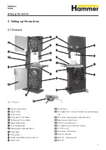
Page 15: ...indicator window BUOn Off switch CLLock wheel Wheel door CMVacuum connector CNTable tilt clamping lever COTable tilt Fig 2 Overview Machine base frame Upper wheel Lower wheel Rising part of saw blade...

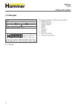
Page 16: ...ber Voltage Phases Frequency Capacity Electricity Year of construction Particulars for the motor Fig 3 Data plate 16 Baujahr year of constr annee de constr A KW HZ PH V NR TYPE Made by Hammer AUSTRIA...

Page 17: ...damage Only operate the machine in ambient temperatures from 10 to 40 C If the instructions are not followed damage may occur during storage Ensure that there is sufficient space for working around t...

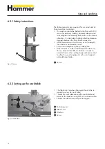
Page 18: ...place lighting is adequate If the machine is to be installed between other ma chines leave at least 80 cm distance in order to avoid collisions when cutting large work pieces and to allow the use of e...

Page 19: ...at hand Before switching on the machine always check to make sure that there are no other persons in the immediate vicinity of the machine During operation When changing to another workpiece or when t...

Page 20: ...ry work is completed For this reason the instructions for adjusting fitting and operating see the corresponding chapters must be read before switching on the machine Operation Fig 6 On and Off switch...

Page 21: ...op screw Determine the exact angle using a 90 triangle If the 90 in the initial position is not correct adjust the stop screw accordingly Check the 90 angle once the clamping lever is back in place 7...

Page 22: ...lever Positioning pin Table insert Hand wheel Clamping lever Check the saw blade tension and if required adjust with the hand wheel The values refer to the saw blade width Fig 10 Scale Scale Hand whe...

Page 23: ...tick as depicted in Fig 13 to prevent your hands from coming too close to the saw blade 7 4 5 Cutting round work pieces in the transverse direction 7 4 6 Longitudinal cut of narrow or thin work pieces...

Page 24: ...Circular cuts Use auxiliary equipment as depicted in the figure Fig 17 Cross cut 7 4 9 Circular cuts 7 4 10 Diagonal cross cuts of rectangular work pieces 7 4 8 Angular cuts Use auxiliary equipment as...

Page 25: ...oo small the blade will overheat and rupture Do not use kinked ruptured or bent saw blades 7 5 1 Blade selection and maintenance For soft wood the set should be a max of twice the thickness of the saw...

Page 26: ...ackwards whilst cutting To adjust the position of the rollers simply loosen the clamping screw 7 5 2 Adjusting the saw blade guide Do not change settings whilst the machine is in opera tion The upper...

Page 27: ...left lying around may be the cause of accidents Install the safety equipment according to the instruc tions and check that it functions properly Warning Danger electric current Work on electrical fitt...

Page 28: ...ds in the centre using a load up to Fig 21 Drive belts Nut 1 Nut 2 8 3 1 Adjusting the belt tension 3 4 kg The belt deflection should not exceed 5 6 mm Loosen nut The tension of the belt can be adjust...

Page 29: ...se of a fault Stricktly speaking In the event of a breakdown which creates danger for either personell or equipment the machine should be stopped immediately using the emergency stop Also disconnect m...

Page 30: ...tch if present is unlocked Check that the air brake switch is in the correct position or if a Y switch is present check that it is set to 0 Contact an electrician Contact an electrician Incorrect shar...

Page 31: ...ma terial to be cut or due to not releasing the blade tension when machine is idle will cause the saw blade to be overloaded The wheels are not aligned with one another Can occur due to unauthorised a...

Page 32: ...Circuit diagram Bandsaw N4400 10 Circuit diagram 10 1 Safety instructions Fig 22 Circuit diagram 1x 230 V 32...

Page 33: ...Bandsaw N4400 33...

Page 34: ...504 15 541 Schlauch 18 440A SICHERHEITSSECHSKANTMUTTER M6 19 504 15 465 Fl gelgriff M6x20 20 404D SCHEIBE M8 VERZINKT 21 504 15 497 Schutzabdeckung 22 504 15 502 untere T r 23 504 15 522 Gewindemutte...

Page 35: ...04 15 532 St tzseil 12 504 15 469 INBUSSCHRAUBE M412 13 402IA SKT MUTTER M4 VERZINKT FLACH 14 504 15 537 Tischeinsatz 15 504 15 535 Tisch 16 406EA SCHEIBE M10 VERZINKT 17 401F SKT MUTTER M10 VERZINKT...

Page 36: ...M6X20 SCHWARZ 8 406C SCHEIBE M4 VERZINKT 9 423BB INBUSSCHRAUBE M6X10 SCHWARZ 10 504 15 531 Sprungplatte 11 418CI SKT SCHRAUBE M6X16 VERZINKT 12 504 15 465 Fl gelgriff M6x20 13 504 15 522 Gewindemutter...

Page 37: ...9 504 15 456 S gebandauflage N4400 lt Zg 503 007 028 10 504 15 486 Sicherungsring 11 432G RILLENKUGELLAGER 6205 ZZ 12 504 15 528 Distanzscheibe 13 504 15 545 oberes Antriebsrad 14 406EA SCHEIBE M10 VE...

Page 38: ...orhebel 5 406EA SCHEIBE M10 VERZINKT 6 418EJ SKT SCHRAUBE M10X60 SCHWARZ 7 418EA SKT SCHRAUBE M10X20 SCHWARZ 8 407EA FEDERRING M10 VERZINKT 9 504 15 504 unteres Antriebsrad 10 504 15 486 Sicherungsrin...

Page 39: ...471 Blechschraube 5 418AC SKT SCHRAUBE M4X16 VERZINKT 6 504 15 454 Elektroschaltger t f N4400 3x400 50Hz 6 504 15 455 Elektroschaltger t f N4400 1x230 50Hz 7 504 15 505 unteres Antriebsaggregat 8 504...

Page 40: ...cut along a line 22 Longitudinal cut of narrow or thin work pieces 23 Lower blade guide 26 Lubrication 27 M Maintenance 27 N Noise emissions 13 O Operation 19 Other risks 10 Overview 15 P Parallel cut...

Page 41: ......

Page 42: ...KR Felder Str 1 A 6060 Hall in Tirol Tel 43 0 52 23 45 0 90 Fax 43 0 52 23 45 0 99 Email info hammer at Internet www hammer at...

Page 43: ...nd to my address subject to your delivery and payment conditions Email Address Yes please send me your Newsletter In this position is your Warranty Card After sending in your warranty card you will re...

Page 44: ...ilability time Email Address Yes please send me your Newsletter Electrical Equipment V PH Hz A HAMMER Qualified personnel HAMMER Operation manual KW Year of Manufacture Machine Number Machine type Rec...

Reviews: