background image

HWC - SERIES

REV.

BUL87423

C

INSTRUCTIONS FOR

HWC

PAGE    OF 9

8

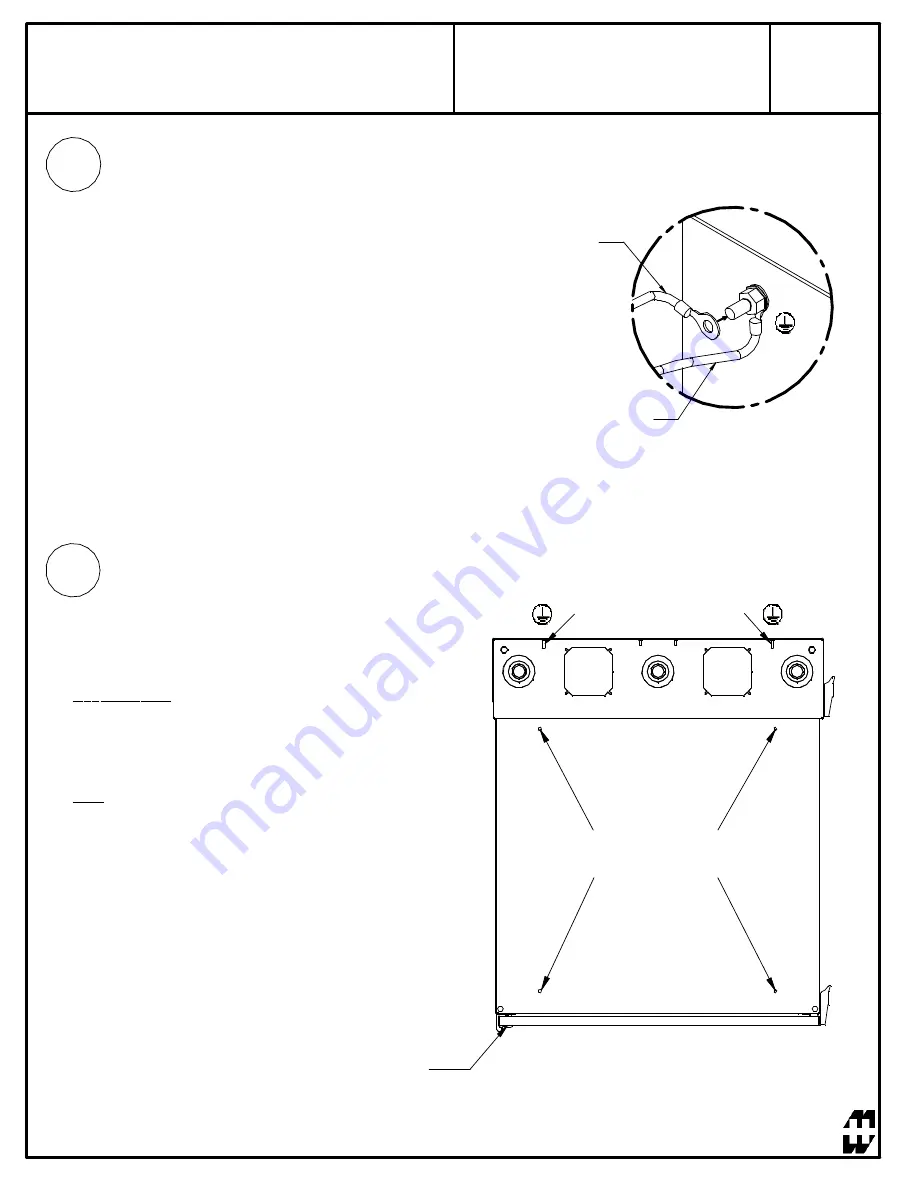
Main Protective Grounding

When grounding the rack system or enclosure it is essential
that the main protective ground is connected and secured
first with its own nut before any bonding connections are
made on top. (Figure 2)

Bonding Connections

Centre Section: Attach bonding wire found in ground kit to a
centre section bonding stud, closest to the hinged side of the
enclosure, using the ring terminal and hardware provided.
Attach opposite end of wire to the nearest PET on the rear
section.

Door: Attach bonding wire to the door stud using the same
method described above. Attach the opposite end to the
nearest centre section bonding stud.

Bonding Connection

Protective Earth Ground

Figure 2

2

3

Top View

Rear Section PETs

Center Section

Bonding Studs

Door Bonding Studs

Summary of Contents for HWC Series

Page 1: ...ES INSTRUCTIONS FOR HWC 1 visit our website visitez notre site Web www hammondmfg com Item Number Title Quantity 1 HWC REAR MOUNT ASSY 1 2 HWC CENTRE SECTION 1 3 HWC RAIL TAPPED 2 4 HWC WINDOW DOOR AS...

Page 2: ...rdance with Article 250 of the National Electric Code To reduce risk of personal injury and product damage always ensure a a sufficient amount of personnel are present when loading unloading and movin...

Page 3: ...INSTRUCTIONS FOR HWC 3 visit our website visitez notre site Web www hammondmfg com 1 TOOL BOX LEVEL NIVEAU WALLMOUNT INSTRUCTIONS OPTIONAL Remove front section of wallmount to allow for an easier inst...

Page 4: ...rews Mount back pan using 3 8 dia lag bolts and standard flat washers 16 TEMPLATE MOD LE 2 LEVEL NIVEAU FRAN AIS Les diff rents mat riaux de paroi murale n cessitent diff rents types de vis Monter l a...

Page 5: ...HWC SERIES REV BUL87423 C INSTRUCTIONS FOR HWC PAGE OF 9 5 4...

Page 6: ...HWC SERIES REV BUL87423 C INSTRUCTIONS FOR HWC PAGE OF 9 6 REVERSE MIDDLE SECTION INSTRUCTIONS 1 2 3 180v...

Page 7: ...ECTION SHALL BE ATTACHED FIGURE 1 NOTE ALL PROTECTIVE EARTH AND BONDING CONNECTIONS SHALL BE IN ACCORDANCE WITH ARTICLE 250 OF THE NATIONAL ELECTRIC CODE 1 Included within optional grounding kit GRDKI...

Page 8: ...ion Attach bonding wire found in ground kit to a centre section bonding stud closest to the hinged side of the enclosure using the ring terminal and hardware provided Attach opposite end of wire to th...

Page 9: ...nduits and fan mounting Proper Removal of Knock Outs When removing an inner knock out with the intent to leave the larger intact ensure the force is applied to the weakest area of the ring This is acc...

Reviews: