#3300P
#3300WP
#3300P, #3300WP
3. DISASSEMBLY PROCEDURE
2/2
Fig. 12-E
Fig 12-D,E
Fig. 12-C
Link Drive
Pin.
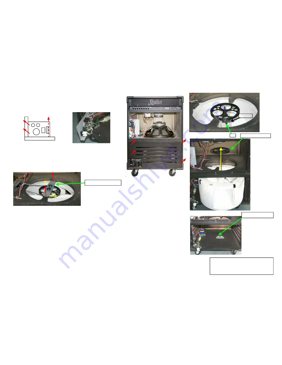
9. Remove the Bottom Rear panel.
Pull the panel up from the unit after removing the 4 tapping screws (type-1 truss,
Ø4x30). Slide it down when remounting.
Fig 10-1
Fig 10-2
10. Removing the Power Switch Panel.
Remove the 3 tapping screws (type-1 truss, Ø4x16) (2 horizontal,
1 vertical).
If necessary, remove the 2 GND wirings inserted to the Faston terminal.
Turn the UP Bearing Ass'y.
11. How to change the wide Drum Rotor Belt.
First remove the Belt by tilting in the Lower Motor. After removing the
2 screws W Sems (P=3, M4x30), turn and detach the UP Bearing Ass'y
from the Cabinet.
Take out the Belt from the opening of this Cabinet, and replace it with a
new one.
12. Remove the Drum Rotor.
NOTE: Don't let an unexperienced service staff remove the Drum Rotor.
It requires a certain level of technique to put the shaft into the
Lower Bearing Ass'y at the assembly.
A, Remove the 15" Speaker and the Power Switch Panel.
B, Pull out the UP Bearing Ass'y from the Pulley Ass'y.
C, Pull out the rubber Link Drive (for conducting the rotation of the pulley
to the rotor) from the Rotor Pin,
D, Slowly take it out from the Drum Rotor by turning
the Pulley and the Shaft.
E, When the Shaft is pulled out from the Lower Bearing Ass'y, move the Drum Rotor
to the front.
F, Then slide it from underneath the Horn Driver, and take out the Shaft from the
Rotor. Finally, take out the Drum Rotor from the Cabinet.
Fig 11
Shaft and Pulley Ass'y
LOWER Bearing ASS'Y
Fig. 9


