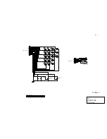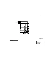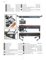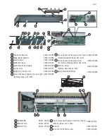
11. XK-1 Technical description
1.
Switching power supply (JRC AES10-5)
This board commutates the AC power input and su5V
power. This +5V power is used as a MGH-94A’s power source.
2.
Main, CPU, VASE, DSP and JACK on the board MGH-94A
2 CPUs, 2 VASE3s (sound generator), DSP, D/A converter and
jacks are all built in the MGH-94A. The Main CPU and the VASE 3
simulate the tone wheel generator and the multi-contact keying to
provide the effects.
2-1.Main CPU
The U1 means the Main CPU (SH7144). This CPU communicates to
the switch scan, each switch’s operation, the LCD display, the
analog-digital conversion for drawbars and volume, the VASE3, the
DSP control and the SUB CPU.
2-2. SUB CPU
The U41 means the SUB CPU (3024). This CPU does key-scan and
communicates with the Main CPU.
2-3. Main memory
Main soft wear is stored at the 16bit flash memory of the U14
(29LV160CBTC). The U15 and U44, 1Mbit SRAM is supplied VCC by
a battery and saves the each parameter. It is also used for a
workspace.
2-4. System reset
The U11 constantly mo3.3V and tells the Main CPU to reset
when the voltage is reduced. This circuit helps to switch the back
up SRAM power to the battery(BT1) at the same time.
2-5. VASE3 sound generator
The U29 and 30 is a sound generator LSI and each one has 64
simultaneous tones (Total is 128 tones). 96 out of 128 tones are


