*#1
:-
Owner’s Manual
110
Frequency
Gain
TC
100Hz
0dB
+3dB
-15dB
-9dB
-3dB
1kHz
10kHz
0
-1
-5
-9
+9
Frequency
Gain
0dB
+9dB
-9dB
BASS
Gain
TREBLE
Gain
TREBLE
Freq.
BASS
Freq.
20 - 200
4k - 8k
MIDDLE
Gain
MIDDLE
Freq.
250 - 3.1k
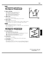
Diagram of Tone Control
Diagram of 3-bands Equalizer
EQUALIZ (Equalizer)
In this mode, you adjust the settings for the Equalizer.
An Equalizer is used to adjust the tonal quality.
Th
e XK-5’s built-in Equalizer consists
of 3 bands and a recreation of the unique “tone” control that was part of the B-3/C-3.
Th
e Bass and Treble bands are handled by “shelf” equalizers, and the Mid band is
handled by parametric control.
PATCH EQUALIZER
❶
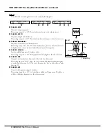
TONE CONTROL(P)
Th
is is a simulated B-3/C-3 TONE CONTROL. Its response is unique, but its basic
response is to gently cut the overall treble above 200Hz.
Th
e setting range is -9 to +9, and it becomes neutral when set at “0”. “-1” corresponds
to the maximum of the B-3/C-3 tone control, “-5”, the middle, “-9”, the minimum.
Th
e tone control found on the B-3/C-3, was only available at “minus” settings, but
here you are able to “plus” the settings as well.
PATCH EQUALIZER AND MASTER EQUALIZER
❷, ❽
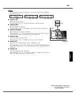
GAIN - BASS (P), (G)
❸, ❾
GAIN - MIDDLE (P), (G)
❹, ❿
GAIN - TREBLE (P), (G)
Adjusts the Boost/Cut of Bass, Mid-range and Treble respectively.
Th
e setting range is -9 to +9. It is
fl
at at 0.
❺, ⓫
FREQUENCY - BASS (P), (G)
❻, ⓬
FREQUENCY - MIDDLE (P), (G)
❼, ⓭
FREQUENCY - TREBLE (P), (G)
Adjusts the center frequency (MIDDLE) / turnover frequency (BASS, TREBLE) to be
attenuated.
Th
e setting range is 20Hz - 200Hz for BASS, 250Hz - 3.1kHz for MIDDLE, 4.0kHz -
8.0kHz for TREBLE.
The sound may distort if gains are raised too high. Adjust accordingly.
NOTE: The parameter with (P) indicated is a patch parameter, and is recorded to each patch. (G)
indicates “global parameter”, which is recorded upon being set, and is common with each
patch.
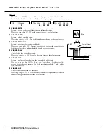
TURNOVER FREQUENCY
The MIDDLE of this equalizer controls a point
of frequency. This is called center frequency.
The BASS (or TREBLE) controls lower (or high-
er) than speci
fi
ed frequency. This is called
turnover frequency.
PATCH PARAMETERS
The equalizer is designed to be a patch param-
eter to be actively utilized as a part of sound
making parameter.
Use the Master Equalizer (P. 33) for tonal com-
pensation to match the performance stage.
MENU/EXIT
S
S
S
ENTER
To locate this mode:
See “Function mode” (P. 68) for operation details.
❶
❷
❸
❹
❺
❻
❼
❽
❾
❿
⓫
⓬
⓭
Summary of Contents for XK-5
Page 5: ...5 Introduction INTRODUCTION...
Page 14: ...1 Owner s Manual 14...
Page 15: ...15 HOOK UP...
Page 25: ...25 POWER ON AND PLAY...
Page 39: ...39 SETTING UP...
Page 63: ...63 USING THE CONTROL PANEL...
Page 73: ...73 SETTING THE PARAMETERS...
Page 101: ...101 Parameters WILL BE DESTROYED...
Page 114: ...1 Owner s Manual 114...
Page 115: ...115 MIDI USB...
Page 130: ...1 Owner s Manual 130...
Page 131: ...131 SAVE THE SETUP...
Page 144: ...1 Owner s Manual 144...
Page 145: ...145 FREQUENTLY ASKED QUESTIONS...
Page 147: ...147 APPENDIX...
Page 160: ...1 Owner s Manual 160...
Page 162: ...1 Owner s Manual 162...
Page 163: ...163 Appendix...
Page 168: ...1 Owner s Manual 168...
Page 170: ...Printed in Japan SUZUKI MUSICAL INST MFG CO LTD Hamamatsu Japan 00457 40195 V1 00 151006...

