background image

159

Appendix

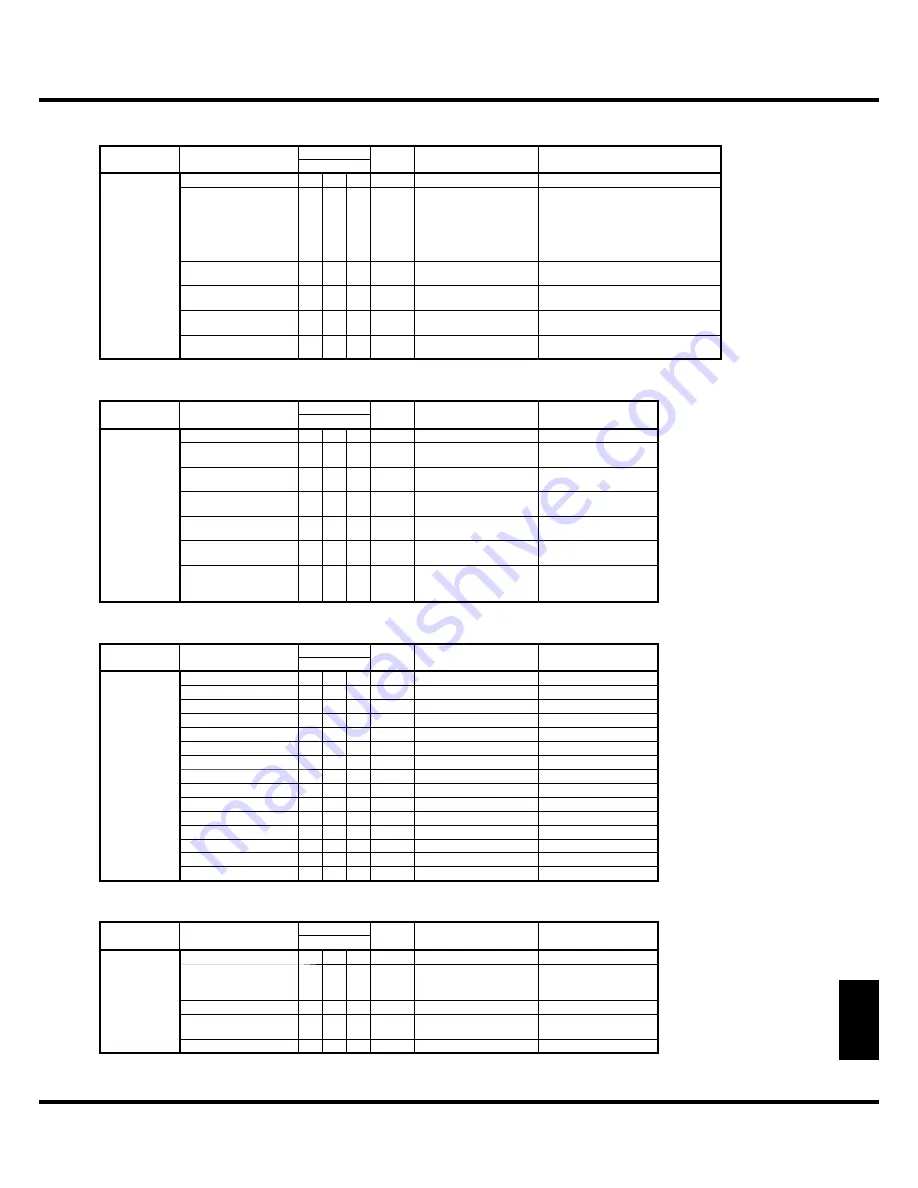
TONE WHEEL PARAMETERS

Category

Parameter

SysEx Address SysEx

Length

Data

Description

MSB to LSB

T e m p o r a r y 
Tonewheels

Name

02

s0

00

0A

(10 characters)

Level

02

s1

tt

01

00 - 16

(-20 - +2 [dB])

s: Tonewheel set

0 = A-100 

1 = B-3

2 = C-3

3 = Mellow

tt: Tonewheel number; 00 - 5F (#01 - #96)

HPF Cut O

ff

  Freq.

02

s2

tt

01

00 - 7F

(0 - 127)

LPF Cut O

ff

  Freq.

02

s3

tt

01

00 - 7F

(0 - 127)

LPF Resonance

02

s4

tt

02

00 00 - 0C 08

(-100 - +100)

nibblized hexadecimal

06 04 = 0

Leak Level

04

tt

ll

01

00 - 7F

(0 - 127)

tt: Fundamental TW #;  00 - 3B (#01 - 60)

ll: Leaking TW #; 3C - 5A (#61 - #91)

PIPE PARAMETERS

Category

Parameter

SysEx Address SysEx

Length

Data

Description

MSB to LSB

Pipes

Name

05

00

00

0A

(10 characters)

Volume

05

01

pp

01

00 - 7F

pp: Pipe number

00 - 13 (#01 - #20)

Detune

05

02

pp

01

0E - 40 - 72

(-50 - 0 - +50)

Chi

ff


05

03

pp

01

00 - 03

(O

ff

 , Soft, Normal, Loud)

Cut O

ff

  Freq.

05

04

pp

01

00 - 40

(-64 - 0)

Pan - Direction

05

05

pp

01

00 - 40 - 7F

(L64 - Center - R63)

Pan - Imageing

05

06

pp

01

00 - 04

(Fixed, L-R, R-L, Pyramid, 

Inverted Pyramid)

PEDAL SUB DRAWBARS PARAMETERS

Category

Parameter

SysEx Address SysEx

Length

Data

Description

MSB to LSB

Temporary Ped-
al Sub Drawbars

Name

06

s0

00

0A

(10 characters)

s: Pedal Sub DB set

Normal 16’ - 16’

06

s1

01

01

00 - 08 (0 - 8)

Normal 16’ - 5 1/3’

06

s1

02

01

00 - 08 (0 - 8)

Normal 16’ - 8’

06

s1

03

01

00 - 08 (0 - 8)

Normal 16’ - 4’

06

s1

04

01

00 - 08 (0 - 8)

Normal 16’ - 2 2/3’

06

s1

05

01

00 - 08 (0 - 8)

Normal 16’ - 2’

06

s1

06

01

00 - 08 (0 - 8)

Normal 16’ - 1 3/5’

06

s1

07

01

00 - 08 (0 - 8)

Normal 16’ - 1 1/3’

06

s1

08

01

00 - 08 (0 - 8)

Normal 8’ - 8’

06

s1

09

01

00 - 08 (0 - 8)

Normal 8’ - 4’

06

s1

0A

01

00 - 08 (0 - 8)

Normal 8’ - 2 2/3’

06

s1

0B

01

00 - 08 (0 - 8)

Normal 8’ - 2’

06

s1

0C

01

00 - 08 (0 - 8)

Normal 8’ - 1 3/5’

06

s1

0D

01

00 - 08 (0 - 8)

Normal 8’ - 1 1/3’

06

s1

0E

01

00 - 08 (0 - 8)

CONTACT PARAMETERS

Category

Parameter

SysEx Address SysEx

Length

Data

Description

MSB to LSB

Temporary Con-
tacts

Name

1s

00

00

0A

(10 characters)

s: Contacts set

Attack Rate Center

1s

t1

kk

02

00 00 - 01 7F

(0 - 255)

t: Footage

(0 = 16’, 1 = 5 1/3’...)

kk: MIDI note number

Attack Rate Variation

1s

t2

kk

01

00 - 7F

Release Rate Center

1s

t3

kk

02

00 00 - 00 7F

(0 - 255)

Release Rate Variation

1s

t4

kk

02

00 - 7F

™

  LPF/HPF は無くなるのか?

Summary of Contents for XK-5

Page 1: ...e time to read this manual completely to take full advantage of the many features of your XK 5 and please retain it for future refer ence LESLIE UPPER SUSTAIN PEDAL LOWER PEDALTO SPLIT TRANSPOSE BYPAS...

Page 2: ...nation to avoid injury from tip over Unplug this apparatus during lightning storms or when unused for long periods of time Refer all servicing to qualified service personnel Servicing is required when...

Page 3: ...AFELY THERE IS A DANGER OF SEVERE ELECTRICAL SHOCK IFTHE CUT OFF PLUG IS INSERTED INTO ANY 13 AMP SOCKET If a new plug is to be attached to the cord please observe the wiring code as shown below If in...

Page 4: ...ilar materials to remain on the unit for long periods of time Such objects can dis color or otherwise harmfully affect the finish Do not paste stickers decals or the like to this instrument Peeling su...

Page 5: ...5 Introduction INTRODUCTION...

Page 6: ...ff 29 Favorites is On 29 SWITCHING FAVORITE ON AND OFF 30 ASSIGN A PATCH TO A PRESET KEY 31 USING CONTROLLERS 32 EXPRESSION PEDAL 32 FOOT SWITCH 32 LESLIE MODE SWITCH 32 TEMPORARY EQUALIZING MASTER EQ...

Page 7: ...ACTS OF THE B 3 C 3 AND VIRTUAL CONTACTS 95 PED REG Pedal Registration Sub Drawbars 96 RECORD THE SUB DRAWBARS 97 PIPE 98 RECORD THE CUSTOM PIPES 100 AMP EFF Pre Amplifier Multi Effects 102 OVERDRIVE...

Page 8: ...AND SECURING THE POWER 142 THE UPDATOR DOES NOT FOUND 142 FREQUENTLY ASKED QUES TIONS 145 TROUBLESHOOTING 146 APPENDIX 147 MIDI TEMPLATE 148 MIDI TEMPLATE 148 FACTORY PATCHES 149 MIDI INFORMATION 150...

Page 9: ...E VIBRATO A digital and programmable Leslie is available for the Drawbar voices as well as the tradi tional Chorus Vibrato as used on the legendary B 3 C 3 AMP SIMULATOR EFFECTS The tube circuits simu...

Page 10: ...s Allocates the Preset keys and VALUE knob which Upper or Lower to select a Patch P 28 BANK button Selects 10 s digit of the Patch or select the Bank of the Favor ites P 28 RECORD button Records a Pat...

Page 11: ...On and the Preset key A is selected LOWER B DRAWBARS These Drawbars for Upper part which enabled with the Preset Select LOWER button is in On and the Preset key B is selected PERCUSSION ON button Add...

Page 12: ...TH knob Adjusts the depth of the Reverb effect P 56 KEYBOARD KEYBOARD 61 notes of musical keys 12 notes of Preset keys water fall type non weighted virtual multi contact keyboard P 95 ANGLED RECESS HE...

Page 13: ...edal separately purchased EXP 100F to controlling the volume while playing P 17 FOOT CONTROLLER 1 jack FOOT CONTROLLER 2 jack Connects the foot switch separately purchased FS 9H or Ex pression pedal s...

Page 14: ...1 Owner s Manual 14...

Page 15: ...15 HOOK UP...

Page 16: ...pment OFF before connecting amps or headphones L MONO LINE OUT USB MIDI R CTRL 1 CTRL 2 PEDAL EXP ONLY EXP 100F NORM POLARITY REV OTHER LOWER TO HOST PEDAL IN 2 IN 1 OUT FOOT CONTROLLER NORM POLARITY...

Page 17: ...R L MONO LINE OUT R CTRL 1 CTRL 2 PEDAL EXP ONLY XP 100F NORM POLARITY REV LESLIE 11 PIN FOOT CONTROLLER NORM POLARITY REV UPPER BANK KEY PATCH PEDAL LOWER UPPER BANK KEY PATCH PEDAL LOWER 1 Connect t...

Page 18: ...he keyboard channel UPPER and the Leslie MIDI channel to the same channel P 128 When this unit detects that the Leslie speaker is connected the Leslie parameters sent through MIDI from this unit are s...

Page 19: ...y as 3 channel type Leslie speaker system to use dry sound also with ad ditional stationary speakers which connected to the LINE OUT jacks Following step 1 to 3 above 4 Repeat ON OFF the BYPASS button...

Page 20: ...d Refer to the operation manual of the XLK 5 and XPK 250 as required 3 KEYBOARDS USING XLK 5 AND XPK 250 KEYBOARD PHONES HEAD CU 1 XLK 3R USE PK 25R ONLY KEYBOARD USB MIDI OTHER LOWER FLASH DRIVE TO H...

Page 21: ...s compliant with the XK 5 are avail able from our sales dealers MIDI pedalboard XPK 100 13 keys MIDI pedalboard XPK 200 20 keys XPK 200L 20 long keys HOW WORKS OF MIDI KEY BOARD If a MIDI template whi...

Page 22: ...only the keyboard expansion See P 16 for the basic hook up of the power source audio etc 2 Switch on this keyboard Refer to the operation manual of the XLK 5 as required KEYBOARD PHONES HEAD CU 1 XLK...

Page 23: ...r to the operation manual of the MIDI keyboards as required MIDI Keyboard MIDI OUT L MONO LINE OUT USB MIDI R CTRL 1 CTRL 2 PEDAL EXP ONLY EXP 100F NORM POLARITY REV OTHER LOWER FLASH DRIVE TO HOST TO...

Page 24: ...tc 2 Switch on this keyboard and recall the MIDI TEMPLATE Basic P 128 1 Refer to the operation manual of the MIDI keyboards as required MIDI Pedalboard IN OUT L MONO LINE OUT USB MIDI R CTRL 1 CTRL 2...

Page 25: ...25 POWER ON AND PLAY...

Page 26: ...f the amplifiers etc Reverse the above steps when you switch the power OFF Also be sure to switch the power to a connected amplifier OFF before switching the keyboard OFF POWER ON BACK UP This keyboar...

Page 27: ...per Internal External Zone F and Drawbar Parameters for Upper and Lower Percussion Effects Upper Patch Name ex Stopped Fl 1 Select parts which you wish to recall Press the both UPPER and LOWER of the...

Page 28: ...d WHAT IS PRESET KEYS The Preset Keys are the key group which select the Patch vari ous setting quickly a Preset Key assigned a Patch NOTE Itexplainedon Favorites P 29 relationbetween PresetKey and Pa...

Page 29: ...ches as shown as figure right Recalling the Patch that you experienced on the previous page in fact it recalled a favorite table that fixed between Preset keys and Patches fig ure left ON AND OFF THE...

Page 30: ...T CONTROL UPPER LOWER V 2 V 1 C 2 C 3 V 3 C 1 VIBRATO C D D E F F G G A A B PLAY UPPER BANK KEY PATCH PEDAL LOWER VOLUME MASTER VALUE ENTER C DRAWBAR MENU EXIT CONTROL UPPER LOWER V 2 V 1 C 2 C 3 V 3...

Page 31: ...ER PEDALTO SPLIT TRANSPOSE BYPASS DOWN UP LOWER BANK LOWER PRESET SELECTOR RECORD STOP FAST OCTAVE VOLUME MASTER VALUE ENTER UPPER BANK KEY PATCH PEDAL LOWER C DRAWBAR MENU EXIT CONTROL UPPER LOWER V...

Page 32: ...des of the Leslie effect This switch is high durability for players who switching frequently while playing NOTE There is called Main Echo Switch in the Leslie switches It is un supported in this keybo...

Page 33: ...0 2 MID FREQUENCY Adjusts the center frequency Middle to be attenuated The setting range is 250Hz 3 1kHz 3 MID GAIN Adjusts the Boost Cut of Middle The setting range is 9 to 9 It is flat at 0 4 TREBLE...

Page 34: ...es all the current control panel settings active allowing for real time registration and the creation of new patches Column Initializing Adjust Pre sets When the A and B Preset Keys are pressed not on...

Page 35: ...sion turn the ON button on There are two choices of Percussion Pitch One sounds an oc tave above the note played Second and another sounds a twelfth above Third When the THIRD light is off Second is s...

Page 36: ...ST button This button toggles the mode of the rotor to FAST LED lit or not STOP button This button sets the mode STOP LED lit or SLOW when the FAST button is off BYPASS button To engage the Leslie eff...

Page 37: ...N PEDAL LOWER PEDALTO SPLIT TRANSPOSE DOWN UP LOWER BANK LOWER PRESET SELECTOR RECORD OCTAVE LESLIE UPPER SUSTAIN PEDAL LOWER PEDALTO SPLIT TRANSPOSE BYPASS DOWN UP LOWER BANK LOWER PRESET SELECTOR RE...

Page 38: ...O MAKE YOUR OWN SOUND continued RECORD THE PATCH TO MEMORY All the previous settings can be recorded to any Patch within the range of U00 to U99 Example RECORD TO U32 1 LOCATE THE RECORD MODE Press th...

Page 39: ...39 SETTING UP...

Page 40: ...eslie simulator Leslie Simulator Vibrato Chorus Pre Amplifier TC Equalizer Master Equalizer Virtual Tonewheel Set Pedal Exclusive Oscillator Pedal Drawbars Lower Drawbars Upper Drawbars Percussion Ped...

Page 41: ...rcuit for amplify the audio signal But we can make it overdrive sound by excessive gain with deliberate MULTI EFFECTS The Multi Effects create various effects such as tremolo and Wah EQUALIZER LESLIE...

Page 42: ...duced such as Ace Tone TOP 6 etc using the transistor circuit instead of the Tone Wheels or tubes The circuit system is different from maker to maker or model by model We have repli cated 2 representa...

Page 43: ...E When the organ type is switched at Pipe of the manual part it switched at Pipe of the Pedal part also automatically UPPER BANK KEY PATCH PEDAL LOWER VOLUME MASTER VALUE ENTER C DRAWBAR MENU EXIT CON...

Page 44: ...osition P 80 DRAWBARS ON TONE WHEEL ORGAN The pitch of each Drawbar is as shown above when the middle C is depressed The footage marked legend in front of each Drawbar is derived from the correspond i...

Page 45: ...hird harmonic of the 16 fundamental Normally the tones are built on the 8 fundamental but if you want to add depth to the tone or to expand the playing range by one octave lower build your tones on th...

Page 46: ...000 Clarinet 8 00 6070 540 English Horn 8 00 3682 210 Flugel Horn 8 00 5777 530 French Horn 00 7654 321 Kinura 8 00 0172 786 Oboe 8 00 4764 210 Trombone 8 01 8777 530 Trumpet 8 00 6788 650 Tuba Sonor...

Page 47: ...created at the dawn of the Hammond Organ when it was intended to sound like a pipe or church organ Later on as the Hammond Organ spread throughout Jazz Pop Rock and especially Gospel music Some timel...

Page 48: ...plural pitches The 2 Drawbars on the right are a mini mixer controlling the mellow voice or bright voice as in the vintage combo organ Each or both of the two right hand Draw bars must be pulled in s...

Page 49: ...rgan was tablet equipped with different sounds at various footages On this keyboard the op eration is made with Drawbars instead of tablets At the same footage the tablets gives grow brighter in sound...

Page 50: ...ued DRAWBARS PIPE When using the PIPE organ type the stops are registered through the Drawbars and follow the classic organ layout left to right as follows Flue Mixture and Reed On the UPPER and LOWER...

Page 51: ...physical Drawbar setting If you move any Drawbar its position takes precedence over the recorded registration by CONTROL CONTROL MODE is set at ALWAYS A although the recorded preset is not altered If...

Page 52: ...cussion tone will decay slowly like a bell When it is ON LED is lit the percussion tone will decay rapidly like a xylophone THIRD button Switch the harmonic of the percussion When this button is OFF t...

Page 53: ...Chorus of this page Chorus of Multi Effects Leslie Effect Slow Choral The names look similar but the effects are dif ferent Scanner Amplifier Amplifier Sections Of Vibrato Line SCANNER VIBRATO The Vi...

Page 54: ...rease but harmonics not existed in the original sound are added This is the DISTORTED SOUND The amplifier made of semiconductor circuits as of a transistor comparatively clearly clips However the circ...

Page 55: ...ou can fine tune the parameters of the Leslie effect P 86 BUTTON MODE BYPASS STOP FAST CH 1 CH 3 on board Leslie effect Off Off On Fast Off Off Off Slow Off On On Fast Off On Off Stop On On On Fast By...

Page 56: ...djusted on the control panel P 102 REVERB REVERB ON button Toggles ON LED lit and OFF the Reverb REVERB DEPTH knob Adjusts the amount of the Reverb NOTE There are numerous parameters in the Reverb The...

Page 57: ...lowing points i Between the internal keyboard and the built in sound engines ii Between the MIDI IN and the built in sound engines iii To the External Zones iv When the MIDI pedalboard XPK 100 is conn...

Page 58: ...he UP button holding down the LOWER button To lower LOWER by one octave press the DOWN button holding down the LOWER button Octave of LOWER is at 1 When changing octaves here the status of the Octave...

Page 59: ...FF The keyboard that functions as the Pedal To Lower is the Lower range itself if it is on the XK 5 stand alone and the Lower keyboard if the Lower keyboard is added to the XK 5 The default range of t...

Page 60: ...hich Patches to recall record with the Preset Key On the foregoing organs the correspondence of the Preset Key and the internal memory was fixed but it is freely assignable on this keyboard PRESET KEY...

Page 61: ...E PAGE A If Page A is not displayed locate Page A by pressing T but ton GO TO PATCH FUNCTION MODE Press ENTER and go to PATCH function mode INPUT NAME You can enter a name using up to 10 letters W X b...

Page 62: ...RECORD button The Record mode is displayed SELECT THE PATCH NUMBER Press the ENTER button The patch is confirmed and is dis played as follows for a few seconds Recording Patch When the recording is c...

Page 63: ...63 USING THE CONTROL PANEL...

Page 64: ...PER LOWER V 2 C 2 VIBRATO C D D E F F PLAY WHAT YOU CAN DO ON THE CONTROL PANEL Your access to deep editing the XK 5 All of the parameters and all of the controls not cov ered by the top panel knobs a...

Page 65: ...IN THIS MODE Registration Digits UPPER BANK KEY PATCH PEDAL LOWER VOLUME MASTER VALUE ENTER C DRAWBAR MENU EXIT CONTROL UPPER LOWER V 2 C 2 VIBRATO C D D E F F PLAY The two PLAY modes for displaying...

Page 66: ...m you wish to edit using the direction buttons then press the ENTER button and enter each Function mode HOW TO READ THE DISPLAY OPERATION IN THIS MODE UPPER BANK KEY PATCH PEDAL LOWER VOLUME MASTER VA...

Page 67: ...cs of the Vibrato Chorus P 85 3 LESLIE For custom setting of the on board Leslie effect and sets the external Leslie speaker settings P 86 4 PIPE For custom setting the characteristics of the Pipe sto...

Page 68: ...s can be navigated the same way CURSOR In this example the flashing cursor indicates the value of the fast speed of the Leslie There is another page above or below this page PARAMETER ITEM name PAGE n...

Page 69: ...ng the MENU etc Here as an example let s display the Drawbar Pedal page While holding down the RECORD button press the CON TROL button The display shows Recording Assign for a while You will be able t...

Page 70: ...B PLAY UPPER BANK KEY PATCH PEDAL LOWER VOLUME MASTER VALUE ENTER C DRAWBAR MENU EXIT CONTROL UPPER LOWER V 2 V 1 C 2 C 3 V 3 C 1 VIBRATO C D D E F F G G A A B PLAY 5 6 1 2 4 3 CHANGE THE VALUE PARAM...

Page 71: ...rameter RETURN TO THE PLAY MODE UPPER BANK KEY PATCH PEDAL LOWER VOLUME MASTER VALUE ENTER C DRAWBAR MENU EXIT CONTROL UPPER LOWER V 2 V 1 C 2 C 3 V 3 C 1 VIBRATO C D D E F F G G A A B PLAY LESLIE UPP...

Page 72: ...d This function works listed below MENU EXIT button P 66 is disabled RECORD button P 62 is disabled normally But you can record the Patch Preset Key by switched OFF the Favorite before locking the dis...

Page 73: ...73 SETTING THE PARAMETERS...

Page 74: ...ly with 1 but also with 11 3 13 5 2 22 3 Drawbars LEAK LEVEL OFFSET Sets the total volume of the leakage tone The setting range is 0 silent to 127 maximum UPPER ZONE OCTAVE Set the octave shift for th...

Page 75: ...decay time NOTE You can locate this page by holding down the PEDAL SUSTAIN button as well VELOCITY This allows you to set the response to playing velocity The setting range is OFF and 1 4 At OFF the v...

Page 76: ...tch is recalled PATCH LOAD REGISTRATION B Drawbar registration PATCH LOAD PARAMETERS B The parameters such as organ type or Percussion PATCH LOAD INTERNAL ZONE B The parameters which relating with Int...

Page 77: ...ECORD button It associated between current Patch and the Preset key on the Favorite Table FAVORITE TABLE This is for displaying and changing the Patch referred to each Preset Key This is called Favori...

Page 78: ...P 111 of the Effects at the interval of pressing the foot switch The delay sound goes out while the foot switch is held down DAMPER Holds played notes while the foot switch is depressed as does the da...

Page 79: ...ing range is OFF 40dB to 0dB At OFF the sound totally disappears but at other value points the set volume is kept even if the expression is at minimum EXPRESSION GAIN S Sets the gain range of the conn...

Page 80: ...ot to use the LOWER B Drawbar as an assignable Drawbar In OFF the Drawbar B moves normally and in ON it acts as an assignable Drawbar ASSIGN FOOTAGE G This is for selecting the footage to assign when...

Page 81: ...ning to the previous mode from the mode displayed by the short cut operation The setting range is 4 to 16 seconds At NO the screen will not return to the previous mode DISPLAY POP UP G Sets the interv...

Page 82: ...he EXP 50 20 Expression Pedal connected to the CTRL2 jack set the POLARITY switch at NORM CONTROL CTRL2 MODE at EXPRES SION and then the EXPRESSION SOURCE at EXP PEDAL or BOTH Column EXPRESSION LESLIE...

Page 83: ...TUNE MASTER TUNE This is for tuning the entire keyboard The setting range is A 430 to 450 Hz NOTE Master Tune is a global parameter It is recorded when it is set and is common for each patch MENU EXIT...

Page 84: ...ame KEYBOARD KEY TRACK Attenuates the percussion volume by keyboard position ON The higher the note is the lesser the volume OFF No change in volume DRAWBAR 1 CANCEL Mutes the UPPER 1 Drawbar while us...

Page 85: ...Chorus effect The setting range is 349 475 rpm MIX Sets Mix balance of the Chorus effect C1 C2 C3 The setting range is D64 only the Direct tone no vibrato tone EVEN 63V only the Vibrato tone no direct...

Page 86: ...rotary speaker system 122 Leslie 122 large rotary speaker system PR 40 Hammond PR 40 stationary speaker system SLOW SPEED HORN DRUM L Sets the rotor speed on the Slow mode MENU EXIT S S X X LESLIE In...

Page 87: ...es wider stereophonic At 0 mono MIC CENTER HORN DRUM L Sets the offset between center of two microphones and pivot of the rotor The setting range is 50 to 50 cm The virtual Leslie speaker turns counte...

Page 88: ...hannel of the Left or Main and Right or Aux Sub Animation NOTE This is a system parameter It is recorded upon setting and is common with all patches RECORD THE CUSTOM CABINET Record the Leslie paramet...

Page 89: ...91 8F and F92 8G to F96 8B F means the wheel used for extended fold back The non marked Wheel Number means original wheel from B 3 C 3 To select the Wheel Number select the VALUE knob here or slightl...

Page 90: ...ts the volume of the selected Leakage Wheel The setting range is INF off 73 quiet to 4 loud dB It may limited volume when raise the value as the case may be NOTE The parameters 3 to 10 are Tone Wheel...

Page 91: ...previous page are for determining the Custom Number for recording The Custom Number is selected and used when you play Enter the Custom Name if necessary Press the RECORD button at any page for Tone W...

Page 92: ...USTOM NUMBER P This is for selecting the CUSTOM NUMBER to use or compile The setting range is F1 to F3 not re writable and U1 to U3 re writable The symbol will be displayed when the Contact parameters...

Page 93: ...tack and Release of the virtual contact has bouncing chattering PHYSICAL CONTACT PHYSICAL CONTACT NUMBER CT This is for selecting at which physical contact number to sound the selected Virtual Con tac...

Page 94: ...AIN PEDAL LOWER PEDALTO SPLIT TRANSPOSE BYPASS DOWN UP LOWER BANK LOWER PRESET SELECTOR RECORD STOP FAST OCTAVE RECORD THE CUSTOM CONTACTS The Contact parameters 2 11 of the previous page are for de t...

Page 95: ...es do not make sound at the same time The so called Key Click on Hammond Organs is due to the complication of these phenomena VIRTUAL CONTACTS The VIRTUAL CONTACT KEYBOARD on this unit reproduces thes...

Page 96: ...r to use or compile The setting range is F1 to F3 not re writable and U1 to U3 re writable The symbol will be displayed when the Pedal Registration parameters are edited NOTE This parameter is a Patch...

Page 97: ...ious page are for determining the Custom Number for recording The Cus tom Number is selected and used when you play LESLIE UPPER SUSTAIN PEDAL LOWER PEDALTO SPLIT TRANSPOSE BYPASS DOWN UP LOWER BANK L...

Page 98: ...pitch by cent 1 100 of semitones The setting range is 50 0 50 CHIFF Pi Sets the Chiff noise of beginning of notes OFF No sounds the chiff noise SOFT Sounds the chiff noise slightly MID Sounds the chif...

Page 99: ...ft to Right which according to the keys C C D E E F F G G A B B R L Sounds Right to Left which according to the keys C C D E E F F G G A B B PYR Like the pyramid sounds center to sides which according...

Page 100: ...V 1 C 2 C 3 V 3 C 1 VIBRATO C D D E F F G G PLAY 1 2 3 4 RECORD THE CUSTOM PIPES The Pipe parameters 2 9 of the previous page are for deter mining the Custom Number for recording The Custom Number is...

Page 101: ...101 Parameters WILL BE DESTROYED...

Page 102: ...arameters for the Multi Effects are vary by type following MENU EXIT S S ENTER To locate this mode Or holding either OVERDRIVE EFFECT button for a while See Function mode P 68 for operation details NO...

Page 103: ...Pan applies adjustable modulation to the stereo field This is not applicable if a monophonic one channel amp is used or when the Leslie effect Leslie speaker is used AUTO PAN WAVEFORM Sets which wave...

Page 104: ...ANCE Boosts the cut off frequency range of the Low pass Filter and gives a more pro nounced Wah effect The setting range is 0 to 127 The resonance increases as the value rises Wah Wah WAVEFORM When th...

Page 105: ...7 only the effect comes out RING MODULATOR WAVEFORM When the SOURCE is set at LFO the LFO waveform is set Tri Triangle wave The ring frequency number smoothly varies Sqr Square wave The ring sound sud...

Page 106: ...er values the sound is modulated beyond normal recognition PHASER MANUAL Sets the middle frequency of the phase effect The setting range is 0 to 127 The frequency becomes higher as the value increases...

Page 107: ...y of the effect sound The setting range is 0 to 127 The delay increases as the value is increased FLANGER MIX Adjusts the volume balance between the dry and the effect sound The setting range is 0 to...

Page 108: ...the sound is modulated beyond normal recognition CHORUS DELAY Controls the delay of the effect sound The setting range is 0 to 127 The delay becomes greater as the value increases CHORUS MIX Adjusts...

Page 109: ...elay time The setting range is 10 to 1000 ms DELAY FEED BACK Sets the repetition amount of the effect sound The setting range is 0 to 127 The repetition becomes greater as the value is increased DELAY...

Page 110: ...le to plus the settings as well PATCH EQUALIZER AND MASTER EQUALIZER GAIN BASS P G GAIN MIDDLE P G GAIN TREBLE P G Adjusts the Boost Cut of Bass Mid range and Treble respectively The setting range is...

Page 111: ...ly this parameter sets the delay time The setting range is 4 7 to 2000ms The delay becomes longer as the number value is increased NOTE You can set the delay time with the foot switch P 78 1 DELAY FEE...

Page 112: ...ct the number you want to initialize with the VALUE knob The selecting range is shown as below and ALL All Cus tom Tone Wheels A U1 A 100 U1 A U2 A 100 U2 A U3 A 100 U3 B U1 B 3 U1 similarly C U2 C 3...

Page 113: ...e LINE OUT hooked up only L MONO jack The audio outputs in mono IS ACTIVE LESLIE Shows whether is Leslie speaker system active over LESLIE 11 pin jack The audio outputs LINE OUT jacks when the Leslie...

Page 114: ...1 Owner s Manual 114...

Page 115: ...115 MIDI USB...

Page 116: ...record performances and controls to an external sequencer MIDI IN 1 PEDAL JACK MIDI IN 2 OTHER JACK This jack is used for playing this keyboard from external MIDI equipment USB FLASH DRIVE JACK Connec...

Page 117: ...at what speed Velocity and the strike release Note On Off PROGRAM CHANGE Control Channel Switches the internal patches of this keyboard External Zone Channel Switches the external MIDI equipment s pat...

Page 118: ...hannels transmit the playing information of the Upper Lower and Pedal parts These are used to exchange playing information with an external sequencer The Upper channel transmits keyboard and controlle...

Page 119: ...e Shift part Octave Shift ex zone MIDI Channel Sounding Zone part LC LC LC LC LC LC LC LC LC Local Control Local Control ExZone U3 ExZone U2 ExZone U1 Upper Keyboard Manual Bass Lower Kbd Contacts to...

Page 120: ...fault 4 Start recording of the sequencer DAW 5 Send the memory dump if necessary 6 Start your performance MIDI Keyboard MIDI Pedalboard MIDI OUT MIDI OUT Optional OUT IN MIDI USB MIDI Interface L M LI...

Page 121: ...the MIDI cables by record and playback In the case of XLK 5 as Lower keyboard and XPK 250 as Pedalboard it does not necessary to re hook up the MIDI cables by record and play back if the MIDI cables...

Page 122: ...NE OUT USB MIDI R CTRL 1 CTRL 2 PEDAL EXP ONLY EXP 100F NORM POLARITY REV OTHER LOWER FLASH DRIVE TO HOST TO PEDAL IN 2 IN 1 OUT FOOT CONTROLLER NORM POLARITY REV Set the MIDI template at Use Ex KEYBO...

Page 123: ...REV Mute the parts according to the s Ne Eoard channels to sound onl Yia External Zones Set the MIDI template at Basic Recording a performance to a sequencer DAW 1 Select the MIDI template Use Ex in...

Page 124: ...mance with controlling the External Zones from to the external sequencer via USB Set the LOCAL at OFF Mute the parts according to the V NH ERDUG channels to sound only via External Zones 6HQGLQJ H ERD...

Page 125: ...s our exclusive standard B 75 which transmitting both performance information and power supply Use B 75 cable only for this jack The connectors of this cable are different style between upstream or do...

Page 126: ...his zone MIDI CHANNEL Sets the MIDI send channel 1 to 16 of this zone ZONE LOW ZONE HIGH Sets the keyboard range for playing this zone Set the lower limit with LO and the upper limit with HI NOTE 9 an...

Page 127: ...h controller to send the damper information to this zone OFF Does not send CTRL1 A foot controller which connected CTRL1 jack CTRL2 A foot controller which connected CTRL2 jack ON EXP The foot switch...

Page 128: ...connects between internal keyboard and sound engine and internal keyboard and External Zones Received MIDI messages on the Keyboard channel are re sent by External Zones NRPN This switches the NRPN No...

Page 129: ...se sets whether sending receiving the playing information of the multi contacts When ON each contact information are transmitted by below list regardless of above MIDI channels 11 to 16 Physical Conta...

Page 130: ...1 Owner s Manual 130...

Page 131: ...131 SAVE THE SETUP...

Page 132: ...he rough estimate is 4GB or less and formatted with FAT32 Consult our web site about compat ible USB flash drives in Europe http www hammond eu in The US http www hammondorganco com USB CONNECTOR 1 In...

Page 133: ...E F F G G PLAY UPPER BANK KEY PATCH PEDAL LOWER VOLUME MASTER VALUE ENTER C DRAWBAR MENU EXIT CONTROL UPPER LOWER V 2 V 1 C 2 C 3 V 3 C 1 VIBRATO C D D E F F G G PLAY USB FLASH DRIVE TO HOST TO INITI...

Page 134: ...Parameters for Upper and Lower Coupler and Lower Vibrato and Chorus Lower U00 and Drawbar Parameters for Pedal Percussion Effects Lower Patch Name ex Cello Upper Patch Name ex Stopped Fl U3 U2 U1 Cust...

Page 135: ...display the Menu mode select the page F SYSTEM by using S button Press the ENTER button SYSTEM function mode is lo cated Select the USB page by using S button Switch ON or OFF of whether using Mass S...

Page 136: ...ew Save by using S button at several times or VALUE knob press the ENTER button to decide MENU EXIT S S S S ENTER UPPER BANK KEY PATCH PEDAL LOWER VOLUME MASTER VALUE ENTER C DRAWBAR MENU EXIT CONTROL...

Page 137: ...CONTROL UPPER LOWER V 2 C 2 V 3 C 1 VIBRATO C D D E F F G PLAY UPPER BANK KEY PATCH PEDAL LOWER VOLUME MASTER VALUE ENTER C DRAWBAR MENU EXIT CONTROL UPPER LOWER V 2 C 2 V 3 C 1 VIBRATO C D D E F F G...

Page 138: ...the LOAD mode you are first asked where you wan to load the file Select the USB Flash or the INTERNAL MEM with the VAL UE knob and decide with the ENTER button NOTE If the USB Flash Drive is not inser...

Page 139: ...with showing Loading xxx Please wait The display shows Setup file name again when the load proce dure is finished Press the PLAY button to return to the Play mode HOW TO USE w o Global The Setup w o G...

Page 140: ...t asks stored media Select the USB Flash or Internal Memory by VALUE knob press the ENTER button to decide NOTE This page does not displayed when the USB Flash Drive is not inserted UPPER BANK KEY PAT...

Page 141: ...ER VALUE ENTER C DRAWBAR MENU EXIT CONTROL UPPER LOWER V 2 C 2 V 3 C 1 VIBRATO C D D E F F G PLAY UPPER BANK KEY PATCH PEDAL LOWER VOLUME MASTER VALUE ENTER C DRAWBAR MENU EXIT CONTROL UPPER LOWER V 2...

Page 142: ...files to the system folder of the USB Flash Drive or the Internal Memory When you come to the UPDATE mode you will be first asked to which media you want to read the updator Select the USB Flash or t...

Page 143: ...E ENTER C DRAWBAR MENU EXIT CONTROL UPPER LOWER V 2 C 2 V 3 C 1 VIBRATO C D D E F F G PLAY The updating process is completed when Please power off is displayed Once turn off the power and switch on ag...

Page 144: ...1 Owner s Manual 144...

Page 145: ...145 FREQUENTLY ASKED QUESTIONS...

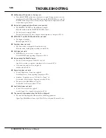
Page 146: ...of each parameter which you wish P 80 Split does not work MIDI IN mode is set at Lower or Upper Set the MIDI IN mode regarding your purpose P 128 No sounding the Pedal To Lower The foot switch is ass...

Page 147: ...147 APPENDIX...

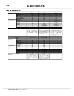
Page 148: ...board with Lower keyboard to MIDI IN OTH ER jack and Pedalboard to MIDI IN PEDAL jack This template is used for record playback the performance to from the external sequencer with XLK 5 XPK 250 and mu...

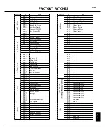
Page 149: ...P35 Mighty Burner P36 Groove Richard P37 Five Spot P38 P39 Jazz B P40 Mr Hammonds Drm P41 Soap Opera P42 Walter s Summer P43 Sweet Ballad P44 Onions P45 Soul Lead Pad P46 Comping Manual P47 All About...

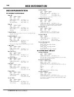
Page 150: ...C 92 Status 2nd Byte 3rd Byte BnH 5CH vvH n MIDI Channel Number 0H FH Ch 1 16 vv Control Value 00H 7FH 0 127 0 63 Off 64 127 On This control change is only for receive NRPN MSB LSB CC 98 99 Status 2nd...

Page 151: ...32H 50 3BH 59 44H 68 4DH 77 05H 5 0EH 14 6 06H 6 0FH 15 18H 24 21H 33 2AH 42 33H 51 3CH 60 45H 69 4EH 78 06H 6 0FH 15 7 07H 7 10H 16 19H 25 22H 34 2BH 43 34H 52 3DH 61 46H 70 4FH 79 07H 7 10H 16 8 08...

Page 152: ...Combi Temp Dump 09H Global Dump 0AH System Dump F7 End Of Exclusive MODE SET Full Parameters Reset Rx only F0 System Exclusive 55 SUZUKI ID dd Device ID 42 Mode ID for DT1 12 Command DT1 40 Address MS...

Page 153: ...01 Off On 01 On Drawbar Regist Lower 6b 01 00 60 01 01 00 01 Off On 01 On Drawbar Regist Pedal 6b 02 00 60 02 01 00 01 Off On 01 On Drawbar Parameters DRAWB 6b 03 00 60 02 01 00 01 Off On 01 On Intern...

Page 154: ...ower 2 07 0D 00 07 0D 01 3E 40 42 2 0 2 External Zone MIDI Channel 4n 00 00 4n 00 01 00 0F 1 16 EXT Switch 4n 01 00 4n 01 01 00 01 Off On Key Range Lo 4n 03 00 4n 03 01 24 60 MIDI note number Key Rang...

Page 155: ...0 05 01 00 40 7F 64 0 63 Custom Pipe 20 06 00 20 06 01 00 04 U1 3 F1 3 Custom Contact 20 07 00 20 07 01 00 04 U1 3 F1 3 Custom TW A 100 20 08 00 20 08 01 00 04 U1 3 F1 3 Custom TW B 3 20 08 00 20 08 0...

Page 156: ...P1 3 Pedal Registration 16 01 03 00 01 00 08 0 8 L P 8 01 03 01 01 00 08 0 8 Organ Effect Leslie Bypass 09 00 00 09 00 01 00 01 Enable Bypass ANI Leslie Fast 09 01 00 09 01 01 00 01 Slow Fast Leslie...

Page 157: ...1 00 7F Multi Effect Parameter 6 3p 0C 00 3p 0C 01 00 7F Multi Effect Parameter 7 3p 0D 00 3p 0D 01 00 7F EQ Bass Gain 3p 0E 00 3p 0E 01 00 09 12 9 0 9 EQ Bass Frequency 3p 0F 00 3p 0F 01 00 0A 20 200...

Page 158: ...1 3 3 LESLIE PARAMETERS SYSTEM PARAMETERS Category Parameter NRPN XK NRPN 21 SysEx Address SysEx Length Data LSB 62 MSB 63 LSB 62 MSB 63 MSB to LSB Cabinet Name 03 00 00 0A 10 Characters Slow Speed H...

Page 159: ...d L R R L Pyramid Inverted Pyramid PEDAL SUB DRAWBARS PARAMETERS Category Parameter SysEx Address SysEx Length Data Description MSB to LSB Temporary Ped al Sub Drawbars Name 06 s0 00 0A 10 characters...

Page 160: ...1 Owner s Manual 160...

Page 161: ...x CUSTOM SETS LIST CUSTOM TONE WHEELS A 100 B 3 C 3 Real B 3 B 3 C 3 80 s Clean 1980 B 3 C 3 Noisy B 3 C 3 Mellow Full Flats Husky Flute Lead Husky CUSTOM CONTACT CUSTOM SUB DRAWBARS CUSTOM CABINETS C...

Page 162: ...1 Owner s Manual 162...

Page 163: ...163 Appendix...

Page 164: ...7 O O Volume 10 O X Pan 11 O O Expression 12 20 80 O O Drawbar Reg Upper 21 29 81 O O Drawbar Reg Lower 33 35 82 O O Drawbar Reg Pedal 48 O O Spring Shock 49 O O Glide 64 O O Damper 69 O O Sustain 92...

Page 165: ...O O Hold 2 69 X O O X Drawbar Reg X CC 80 12 20 Upper 21 29 Lower 33 35 Pedal CC 81 CC 82 Spring Shock 48 X O X X Leslie Fast 92 X O X O RPN 100 101 X X X X NRPN 98 99 X O X X All Notes Off 123 O O O...

Page 166: ...ass Stop Fast Reverb Digital 11 programs Control On Depth Leslie On Reverb Master Equalizer Bass Mid Treble Keymap Buttons Pedal To Lower Split Transpose Octave Down Octave Up Lower Adjustable Coupler...

Page 167: ...ie Channel 18 Leslie Mode Switch 32 Leslie Speaker 18 L MONO 13 Load 138 Lock 72 M Master Equalizer 33 Match 51 Menu Mode 66 MIDI 116 MIDI Pedalboard 21 MIDI Synthesizer 122 MIDI Template 148 Multi E...

Page 168: ...1 Owner s Manual 168...

Page 169: ...sses In the United States Contact HAMMOND SUZUKI USA Inc 743 Annoreno Dr Addison IL 60101 UNITED STATES In Europe contact HAMMOND SUZUKI EUROPE B V IR D S Tuynmanweg 4A 4131 PN Vianen THE NETHERLANDS...

Page 170: ...Printed in Japan SUZUKI MUSICAL INST MFG CO LTD Hamamatsu Japan 00457 40195 V1 00 151006...

Reviews: