11
HAMPTONBAY.COM
Please contact 1-855-HD-HAMPTON for further assistance.
Assembly - Attaching the Fan Blades (continued)
2
Assembly - Attaching the Lights
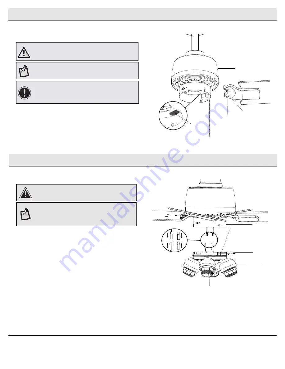
Attaching the light kit fitter assembly
1
□
Remove the three screws (VV) on the switch cup cover of the
light kit fitter assembly (F).
□
Connect the wires from the light kit fitter assembly (F) to the
wires from the switch cup of the fan-motor assembly (E) by
connecting the molded adaptor plugs together (blue to black,
white to white). Carefully tuck all wires and splices into the
switch cup.
□
Align the three holes in the switch cup cover of the light kit
fitter assembly (F) with the three holes in the switch cup
of the fan-motor assembly (E). Make sure the notch in the
switch cup cover of the light kit fitter assembly (F) clears the
reversing switch in the switch cup of the fan-motor assembly
(E). Position the light kit fitter assembly (F) and re-install the
three screws (V V) that were removed in first step to secure
the light kit fitter assembly (F).
CAUTION:
To reduce the risk of electric shock, disconnect
the electrical supply circuit to the fan before installing the
light fixture.
NOTE:
Notice the location of the fan’s slide switch. This is the
switch used to change the fan’s directional rotation. For more
information on the operation of this switch, see
Operating
Your Fan
on page 12.
Fastening the blade assemblies to
the motor
WARNING:
Remove the rubber motor stops on the bottom of
the fan before installing the blades or testing the motor.
NOTE:
Your fan features revolutionary advancements for quick
and easy blade installation, including an alignment post and
captive blade bracket screws.
□
Fasten the blade brackets (H) to the fan-motor assembly (E) by
inserting the alignment post into the slot on the bottom of the
motor and tightening the pre-installed blade bracket screws (OO)
by inserting a screw driver through the access hole (ZZ).
□
Repeat this step for the remaining blade assemblies by rotating
the motor until the next blade bracket screw can be accessed
through the access hole (ZZ) in the switch cup.
IMPORTANT:
The switch cup has an access hole (ZZ) to allow
the screwdriver to reach the screws in the blade bracket.
Position the blade bracket on the motor and tighten by
inserting the screwdriver through the access hole (ZZ).
E
H
ZZ
OO
VV
F
E


