background image

7

HAMPTONBAY.COM

Please contact 1-855-HD-HAMPTON for further assistance.

Assembly - Standard Ceiling Mount

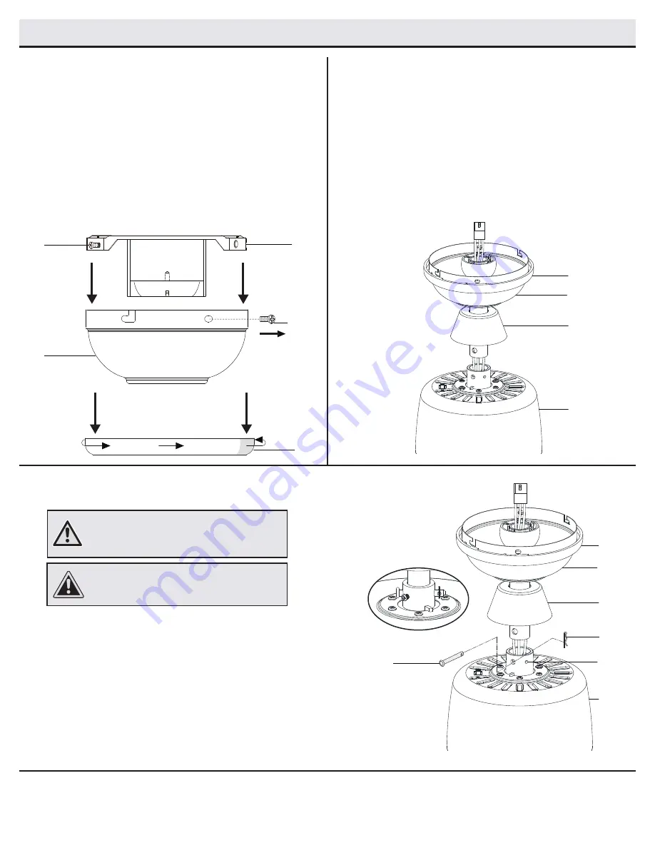
Routing the wires

Assembling the fan

Preparing for mounting


Route the wires exiting the top of the fan motor assembly (E) 
through the center of the canopy ring (FF). Make sure the slots 
on the canopy ring (FF) are on top.


Insert the balldownrod (B) through the canopy (C) and slide 
the decorative motor collar cover (D) onto the end of the ball/ 
downrod (B). Make sure the slots on the canopy (C) are on top.


Route the wires exiting the top of the fan motor assembly (E) 
through the downrod (B) as shown.

2

3

1


Loosen, but do not remove, the setscrews (JJ) on the collar on top 
of the fan-motor assembly (E).


Align the holes at the bottom of the ball/downrod assembly (B) with 
the holes in the collar on top of the fan-motor assembly (E).


Carefully insert the hanger pin (BB) through the holes in the collar 
and ball/downrod assembly (B). Be careful not to jam the hanger 
pin (BB) against the wiring inside the ball/ downrod assembly (B). 


Insert the locking pin (CC) through the hole near the end of the 
hanger pin (BB) until it snaps into its locked position.


Re-tighten the setscrews (JJ) on the collar on top of the fan-motor 
assembly (E). 

CAUTION:

 To ensure wobble-free operation and to 

avoid damage to the fan, the downrod (B) and the 

setscrew (JJ) must be completely tightened.


Remove the canopy ring (FF) from the canopy (C) by turning the 
ring counter clockwise until it unlocks.


Remove the mounting bracket (A) from the canopy (C) by 
loosening the two canopy screws (II) located in the “L shaped” 
slots.


Remove and save the two canopy screws (HH) in the round 
holes. This will enable you to remove the mounting bracket (A). 


WARNING:

 Failure to properly install the locking 

pin (CC) could result in the fan becoming loose 
and possibly falling. 

C

A

HH

II

FF

C

FF

E

CC

D

BB

JJ

C

FF

E

D

Summary of Contents for 1005 919 921

Page 1: ...ugh the purchase of this ceiling fan We strive to continually create quality products designed to enhance your home Visit us online to see our full line of products available for your home improvement...

Page 2: ...ts also referred to as flanges during assembly or after installation Do not insert objects in the path of the blades WARNING To reduce the risk of fire or electric shock do not use this fan with any s...

Page 3: ...removing and reinstalling the product are your responsibility Damage to any part such as by accident misuse improper installation or by affixing any accessories is not covered by this warranty Becaus...

Page 4: ...4 Part Description Quantity AA Plastic wire connecting nuts 3 BB Hanger pin 1 CC Locking pin 1 Pre Installation continued HARDWARE INCLUDED NOTE Hardware not shown to actual size AA BB CC...

Page 5: ...lar cover 1 E Fan motor assembly 1 F Blade 5 Part Description Quantity G Light kit assembly 1 I Receiver 1 J Remote control 1 K Extension lead wire 1 L Battery 1 IMPORTANT This product and or componen...

Page 6: ...t box and support structure must be securely mounted and capable of reliably supporting a minimum of 35 lbs 15 9 kg Use only UL listed outlet boxes marked Acceptable for fan support of 35 lbs 15 9 kg...

Page 7: ...E Carefully insert the hanger pin BB through the holes in the collar and ball downrod assembly B Be careful not to jam the hanger pin BB against the wiring inside the ball downrod assembly B Insert th...

Page 8: ...let box as shown Securely tighten the two mounting screws TT Carefully lift the fan motor assembly E up to the slide on mounting bracket A Insert the ball portion of the ball downrod assembly into the...

Page 9: ...lace as this will damage the hand unit Dispose of used battery properly and keep the battery out of the reach of children 4 Installing the receiver Position the house supply wires AAA to one side of t...

Page 10: ...ting nut AA Connect the receiver I white wire to the household white wire neutral using a wire connecting nut AA Secure each wire connecting nut using electrical tape WARNING To avoid possible electri...

Page 11: ...clockwise to lock in place Assembly Hanging the Fan continued 7 B C D E HH FF A II I Assembly Attaching the Fan Blade Attaching the blade to the motor 1 Attach a blade F to the fan motor housing E by...

Page 12: ...otor assembly E by connecting the molded adaptor plugs together Carefully tuck all wires and splices into the switch cup and connect the safety cable SS from the light kit assembly G to the hook from...

Page 13: ...emote control to operate the speed and lights of your new ceiling fan Speed setting for warm or cool weather depends on factors such as the room size ceiling height number of fans and so on The fan is...

Page 14: ...ove the tip of one of the blades Measure from a point on the center of the blade to the point on the ceiling Rotate the fan until the next blade is positioned for measurement and measure from the same...

Page 15: ...erence by one or more of the following measures Reorient or relocate the receiving antenna Increase the separation between the equipment and receiver Connect the equipment into an outlet on a circuit...

Reviews: