background image

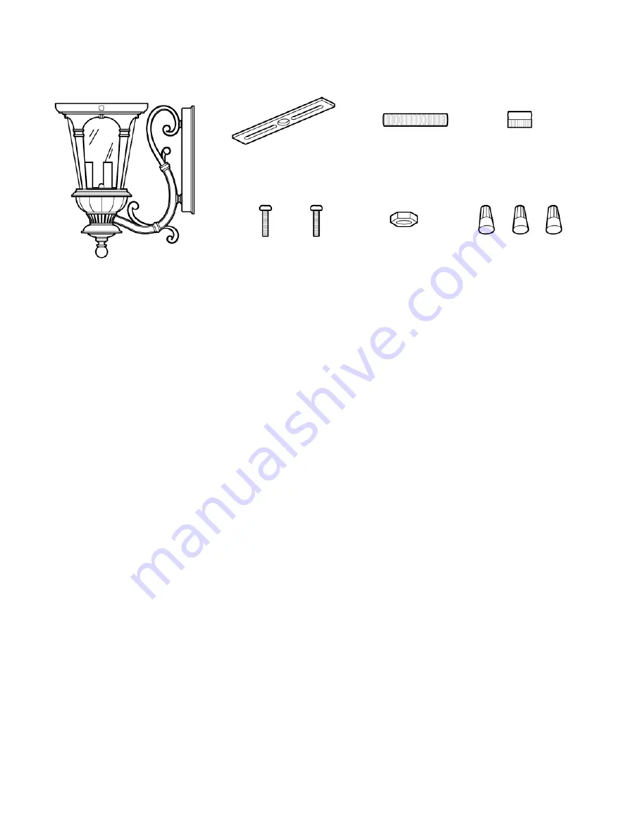
3 ea Wire 

Nuts (#18)

2 ea Bracket Mounting 

Screws (#13)

INSTALLATION INSTRUCTIONS: 

PARTS INCLUDED FOR INSTALLATION (parts are not to 
scale): 

1. Thread the Hex Nut (#12) onto the Nipple (#14).  Thread the Nipple (#14) into the center hole of the 

Mounting Bracket (#11).  Do not tighten the Hex Nut (#12) at this time.

2. Pull the power supply wires out from the Outlet Box (#9), and mount the Mounting Bracket (#11)  to the 

Outlet Box (#9), using the Bracket Mounting Screws (#13). 

3. Attach the Black Supply Wire (#10) to the Black Fixture Wire (#17) and the White Supply Wire (#21) to 

the White Fixture Wire (#18) using Wire Nuts (#19).  Connect the Fixture Ground Wire (#16) and the 
Supply Ground Wire (#20) together using a Wire Nut (#19). Wrap all wire connections with electrical 
tape for a more secure connection.  

Note: If you have electrical questions, consult your local electrical 

code for approved grounding methods.

4. Carefully tuck all Wires and Wire Nuts (#19) into the Outlet Box (#9).  Place the Wall Plate (#15) (of the 

Main Fixture Body (#5)) over the Outlet Box (#9), flush against the wall surface, making sure the Nipple 
(#14) feeds through the hole of the Wall Plate (#15).  Adjust the Nipple (#14) so that it protrudes about 
¼ inch from the surface of the Wall Plate (#15).  Remover the Wall Plate from the wall and tighten the 
Hex Nut (#12) against the Mounting Bracket (#11).  Replace the Wall Plate (#15) over the Outlet Box 
(#9) and thread the Thumb Screw (#6) onto the Nipple (#14) to secure the Wall Plate (#15) against the 
wall. 

5. After installing the fixture, caulk upper 2/3 of the Wall Plate (#15) to mounting surface.  Leave bottom 

1/3 un-caulked for drainage of any water that might leak into the enclosure.  The manufacturer 
recommends a non-drying exterior caulking material.  A good example is a clear silicone rubber sealant 
for exterior use.

6. Installation is complete. Turn on power at the circuit breaker or fuse box.  Turn the light switch on to 

activate the fixture.

1 ea Mounting 

Bracket (#11)

1 ea Nipple (#14)

1 ea Hex 

Nut (#12)

1 ea Thumb 

Screw (#6)

1 ea Main Fixture Body (#5)

Page 6

Summary of Contents for 408-179

Page 1: ...INSTRUCTIONS MANUAL HOME DEPOT SKU 408 179 UPC 046335848276 Page 1 EXTERIOR WALL LANTERN...

Page 2: ...SKU 408 179 or UPC 046335848276 QUESTIONS PROBLEMS MISSING PARTS 1 Easy to install 2 Solid cast aluminum resists elements Thank you for purchasing this Hampton Bay exterior wall lantern This product h...

Page 3: ...and cause possible electrical shock Consult a qualified electrician if needed 3 CONSULT A QUALIFIED ELECTRICIAN IF YOU HAVE ANY ELECTRICAL QUESTIONS If you have any non electrical questions about thi...

Page 4: ...pack the fixture Lay out all parts on a clean surface 2 Before continuing Assembly please proceed to the Installation Instructions 3 Install 3 Light Bulbs 4 in the sockets of the Main Fixture Body 5 D...

Page 5: ...ASSEMBLY 4 Light Bulb 5 Main Fixture Body 7 Hood 8 Hood Screw Page 5...

Page 6: ...ire Nuts 19 into the Outlet Box 9 Place the Wall Plate 15 of the Main Fixture Body 5 over the Outlet Box 9 flush against the wall surface making sure the Nipple 14 feeds through the hole of the Wall P...

Page 7: ...Nut 18 White Fixture Wire 16 Fixture Ground Wire 19 Wire Nut 21 White Supply Wire 10 Black Supply Wire 20 Supply Ground Wire 9 Outlet Box 11 Mounting Bracket 13 Bracket Mounting Screw 12 Hex Nut 17 Bl...

Page 8: ...ar The manufacturer does not warrant and specially disclaims any warranty whether expressed or implied of fitness for a particular purpose other than the warranty contained herein The manufacturer spe...

Page 9: ...MANUAL DE INSTRUCCIONES HOME DEPOT SKU 408 179 UPC 046335848276 Page 9 FAROL DE PARED PARA EXTERIORES...

Page 10: ...D como referencia su SKU 408 179 o UPC 046335848276 PREGUNTAS PROBLEMAS PARTES FALTANTES Page 10 Gracias por comprar este farol de pared para exteriores de Hampton Bay Este producto ha sido fabricado...

Page 11: ...una posible descarga el ctrica Consulte a un electricista calificado si es necesario 3 CONSULTE A UN ELECTRICISA CALIFICADO SI TIENE DUDAS CON LAS CONEXIONES EL CTRICAS Si tiene preguntas acerca de e...

Page 12: ...idado Coloque todas las partes sobre una superficie limpia 2 Antes de continuar con el ensamblaje proceda con las instrucciones de instalaci n 3 Instale tres focos 4 en el portafocos del cuerpo princi...

Page 13: ...ENSAMBLAJE 4 Foco 5 Cuerpo principal del luminario 7 Tapa 8 Tornillo para la tapa Page 13...

Page 14: ...todos los cables y tuercas para cables 19 en la caja de distribuci n 9 Coloque la placa de pared 15 del cuerpo principal del luminario 5 sobre la caja de distribuci n 9 de tal manera que quede al ras...

Page 15: ...del luminario a tierra 19 Tuerca para cables 21 Cable blanco de alimentaci n 10 Cable negro de alimentaci n 20 Cable de alimentaci n a tierra 9 Caja de distribuci n 11 Mounting Bracket 13 Tornillo de...

Page 16: ...xpresa o impl cita de adaptaci n para un fin en particular que no sea la garant a contenida aqu El fabricante renuncia espec ficamente a cualquier responsabilidad y no ser responsable de p rdidas o da...

Page 17: ...INSTRUCTIONS HOME DEPOT UGS N 408 179 CUP N 046335848276 Page 17 LANTERNE MURALE AVEC D EXT RIOR...

Page 18: ...le 408 179 ou le CUP 046335848276 titre de r f rence QUESTIONS PROBL MES PI CES MANQUANTES Merci d avoir achet cette lanterne murale d ext rieur Hampton Bay Cet article a t fabriqu selon les normes de...

Page 19: ...in consultez un lectricien qualifi 3 CONSULTEZ UN LECTRICIEN CERTIFI SI VOUS AVEZ DES QUESTIONS CONCERNANT L INSTALLATION LECTRIQUE Si vous avez des questions autres que celles concernant l installati...

Page 20: ...minaire Placez toutes les pi ces sur une surface propre 2 Avant de poursuivre l assemblage veuillez consulter le mode d installation 3 Installez trois ampoules n 4 dans les douilles du corps du lumina...

Page 21: ...ASSEMBLAGE 4 Ampoule 5 Corps du luminaire 7 Capot 8 Vis du capot Page 21...

Page 22: ...de sortie n 9 l aide de la plaque de montage n 15 du corps du luminaire n 5 en pla ant cette derni re bien plat contre le mur et en veillant faire passer la tige filet e n 14 par le trou central de l...

Page 23: ...re 16 Fil de terre du luminaire 19 Capuchon de connexion 21 Fil d alimentation blanc 10 Fil d alimentation noir 20 Fil de terre de la bo te de sortie 9 Bo te de sortie 11 Plaque de fixation 13 Vis de...

Page 24: ...cite ou implicite de convenance une utilisation sp cifique autre que la pr sente garantie Le fabricant d cline sp cifiquement toute responsabilit et ne peut tre tenu responsable des dommages accessoir...

Reviews: