background image

3

HAMPTONBAY.COM

Please contact 1-877-527-0313 for further assistance.

Pre-Installation

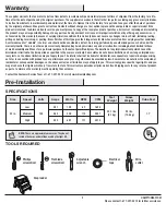
Warranty

The supplier warrants the fan motor to be free from defects in workmanship and material present at time of shipment from the factory for a life-
time after the date of purchase by the original purchaser. The supplier also warrants that all other fan parts, excluding any glass or acrylic blades, 
to be free from defects in workmanship and material at the time of shipment from the factory for a period of one year after the date of purchase 
by the original purchaser. We agree to correct such defects without charge or at our option replace with a comparable or superior model if the 
product is returned. To obtain warranty service, you must present a copy of the receipt as proof of purchase. All costs of removing and reinstalling 
the product are your responsibility. Damage to any part such as by accident or misuse or improper installation or by affixing any accessories, is 
not covered by this warranty. Because of varying climatic conditions this warranty does not cover any changes in brass finish, including rusting, 
pitting, corroding, tarnishing, or peeling. Brass finishes of this type give their longest useful life when protected from varying weather conditions. 
A certain amount of “wobble” is normal and should not be considered a defect. Servicing performed by unauthorized persons shall render the 
warranty invalid. There is no other express warranty. Hampton Bay hereby disclaims any and all warranties, including but not limited to those 
of merchantability and fitness for a particular purpose to the extent permitted by law. The duration of any implied warranty which cannot be 
disclaimed is limited to the time period as specified in the express warranty. Some states do not allow a limitation on how long an implied war-
ranty lasts, so the above limitation may not apply to you. The retailer shall not be liable for incidental, consequential, or special damages arising 
out of or in connection with product use or performance except as may otherwise be accorded by law. Some states do not allow the exclusion of 
incidental or consequential damages, so the above exclusion or limitation may not apply to you. This warranty gives specific legal rights, and you 
may also have other rights which vary from state to state. This warranty supersedes all prior warranties. Shipping costs for any return of product 
as part of a claim on the warranty must be paid by the customer.

Contact the Customer Service Team at 1-877-527-0313 or visit www.HamptonBay.com.

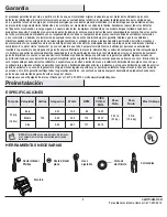
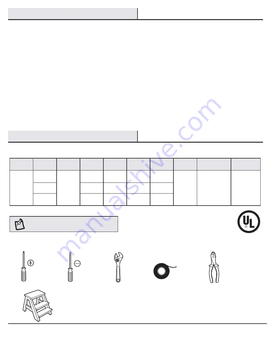
SPECIFICATIONS

TOOLS REQUIRED

NOTE:

 These are approximate measures. They do not

include the amps and wattage used by the light kit.

Phillips 
screwdriver

Flat blade 
screwdriver

Adjustable 
wrench

Electrical 
tape

Wire 
cutter

Step ladder

Size

Speed

Volts

Amps

Watts

RPM

CFM

Net

Weight

Gross

Weight

Cube Feet

52 in.

Low

Medium

High

120

0.21

0.33

0.50

10.2

25.9

60.1

63

110

171

1624

2957

4915

20.1 lbs.

(9.1 kg)

23 lbs.

(10.4 kg)

1.7’

Summary of Contents for 51332

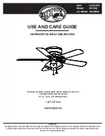
Page 1: ...0313 HAMPTONBAY COM THANK YOU We appreciate the trust and confidence you have placed in Hampton Bay through the purchase of this ceiling fan We strive to continually create quality products designed to enhance your home Visit us online to see our full line of products available for your home improvement needs Thank you for choosing Hampton Bay Item 142 303 Model 51332 UL Model 52 MNL ...

Page 2: ...es Refer to the instructions packaged with the light kits and switches for proper assembly 9 After making electrical connections spliced conductors should be turned upward and pushed carefully up into the outlet box The wires should be spread apart with the grounded conductor and the equipment grounding conductor on one side of the outlet box 10 All setscrews must be checked and retightened where ...

Page 3: ...hall render the warranty invalid There is no other express warranty Hampton Bay hereby disclaims any and all warranties including but not limited to those of merchantability and fitness for a particular purpose to the extent permitted by law The duration of any implied warranty which cannot be disclaimed is limited to the time period as specified in the express warranty Some states do not allow a ...

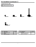
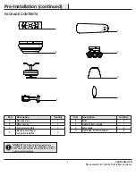
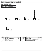
Page 4: ...t screw 16 BB Locknut 3 CC Plastic wire connector 3 Part Description Quantity DD Pull chain 2 EE Extra blade bracket hardware screw and lockwasher 1 hardwarE included NOTE Hardware not shown to actual size AA BB CC DD EE Pre Installation continued ...

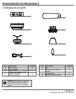
Page 5: ...ange screws pre installed 5 Part Description Quantity E Blade 5 F Light kit fitter assembly 1 G Glass shade 4 H Light bulbs 40 Watt maximum 4 IMPORTANT This product and or components are governed by one or more of the following U S Patents 5 947 436 5 988 580 6 010 110 6 046 416 6 210 117 and other patents pending package contents A B C F D H G E Pre Installation continued ...

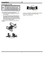
Page 6: ... instructions Disconnect the power by removing the fuses or turning off the circuit breakers Secure the outlet box directly to the building structure Use the appropriate fasteners and materials The outlet box and support structure must be securely mounted and capable of reliably supporting 35 lbs 15 9 kg Use only UL Listed outlet boxes marked Acceptable for Fan Support of 35 lbs 15 9 kg or less Do...

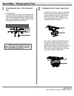
Page 7: ...et on the top of the fan motor assembly C with the hook on the mounting plate A so that it is securely suspended Then connect the wiring to your fan according to step 3 Making the Electrical Connections Once wiring is completed lift the motor bracket on the top of the fan motor assembly C so that the threaded studs II on the mounting plate A pro trude through the slot in the motor bracket Securely...

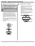
Page 8: ... Connect the fan motor white wire LL to the supply white neutral LL wire using a the plastic wire connector CC Connect the fan motor black KK and blue JJ wires to the supply black hot wire KK using a plastic wire connector CC Spread the wires apart so that the green MM and white LL wires are on one side of the outlet box FF and the black wire KK is on the other side Turn the wire connectors upward...

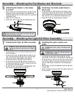
Page 9: ...tall the three screws removed at the beginning of this step to secure the light kit fitter assembly F Insert the glass shade G into the glass holder by carefully squeezing the steel tensioners on the light fixture socket together Gently slide the glass shade G over the steel tensioners Make sure the glass shade G is fully inserted into the socket for a secure fit Repeat these instructions for the ...

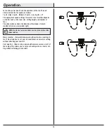
Page 10: ...slide switch controls the direction of the blades forward switch left or reverse switch right Warm weather Forward A downward airflow creates a cooling ef fect This allows you to set your air conditioner on a warmer setting without affecting your comfort Cool weather Reverse An upward airflow moves warm air off of the ceiling This allows you to set your heating unit on a cooler set ting without af...

Page 11: ...he center of the blade to the point on the ceiling Rotate the fan until the next blade is positioned for measurement and measure from the same point on each blade to the ceiling Repeat for each blade Any measurement deviation should be within 1 8 in Run the fan for ten minutes Because of the fan s natural movement some connections may become loose Check the support connections brackets and blade a...

Page 12: ...Questions problems missing parts Before returning to the store call Hampton Bay Customer Service 8 a m 6 p m EST Monday Friday 1 877 527 0313 HAMPTONBAY COM Retain this manual for future use ...

Page 13: ...7 527 0313 HAMPTONBAY COM GRACIAS POR TU COMPRA Apreciamos la confianza que has depositado en Hampton Bay al comprar este ventilador de techo Nos esforzamos para continuamente crear productos de calidad diseñados para tu hogar Visítanos por Internet para ver nuestra línea completa de productos disponibles para las necesidades de mejoras de tu hogar Gracias por elegir Hampton Bay Artículo Núm 142 3...

Page 14: ... interruptores para obtener información sobre el montaje adecuado 9 Después de concluir con las conexiones eléctricas debes voltear los conductores empalmados hacia arriba y meterlos con cuidado en la caja eléctrica Los cables deben estar separados con el cable a tierra y el conductor a tierra del equipo en uno de los lados de la caja eléctrica 10 Todos los tornillos de fijación deben ser verifica...

Page 15: ... autorizadas invalidará la garantía No hay ninguna otra garantía expresa Mediante la presente Hampton Bay se exime de cualquier garantía incluyendo pero sin limitarse a aquellas de comercialización e idoneidad para un fin particular de acuerdo a lo contemplado por la ley La duración de cualquier garantía implícita de la cual no se pueda eximir está limitada al período de tiempo especificado en la ...

Page 16: ...ca 3 CC Conector de cables plástico 3 Pieza Descripción Cantidad DD Cadena para halar 2 EE Herrajes adicionales para montaje de aspas tornillo y arandela de seguridad 1 Herrajes incluidos NOTA No se muestra el tamaño real de los herrajes AA BB CC DD EE Preinstalación continuación ...

Page 17: ...preinstalados 5 Pieza Descripción Cantidad E Aspa 5 F Ensamblaje del soporte del kit de luces 1 G Pantalla de vidrio 4 H Bombillas máximo de 40 Watts 4 IMPORTANTE Este producto y o sus componentes están protegidos por una o más de las siguientes patentes de los EE UU 5 947 436 5 988 580 6 010 110 6 046 416 6 210 117 y otras patentes pendientes contenido del paquete A B C F D H G E Preinstalación c...

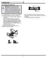
Page 18: ...esconecta la energía retirando los fusibles o apagando los cortacircuitos Fija la caja eléctrica directamente a la estructura del edificio Usa sujetadores y materiales apropiados La caja eléctrica y estructura de soporte deben montarse de forma segura y tener capacidad para sostener de manera confiable 35 lb Usa solamente cajas eléctricas aprobadas por UL marcadas como Aprobada como soporte de ven...

Page 19: ...ntilador C con el gancho de la placa de montaje A para que quede suspendido de forma segura Luego conecta el cableado a tu ventilador según lo indica el paso 3 Cómo Hacer las Conexiones Eléctricas Una vez finalizado el cableado alza el soporte del motor sobre la superficie del ensamblaje del motor del ventilador C para que los pernos roscados II en la placa de montaje A sobresalgan por la ranura e...

Page 20: ...tor del ventilador LL al cable blanco de suministro neutro LL con un conector de plástico para cable CC Conecta los cables negro KK y azul JJ de motor del ventilador al cable negro positivo KK de suministro de energía con un conector de plástico para cable CC Separa los cables de manera que el verde MM y el blanco LL queden de un lado de la caja eléctrica FF y el cable negro KK del otro Gira los c...

Page 21: ...llos que fueron quitados al inicio de este paso para asegurar el ensamblaje del soporte del kit de luces F Inserta la pantalla de vidrio G en el soporte de vidrio apretando con cuidado los tensores de acero sobre el portabombilla de la lámpara Con cuidado desliza la pantalla de vidrio G sobre los tensores de acero Asegúrate de que la pantalla de vidrio G esté totalmente insertada en el portabombil...

Page 22: ...terruptor deslizante controla la dirección de las aspas hacia adelante interruptor hacia la izquierda o reversa interruptor hacia la derecha Clima cálido Hacia adelante Un flujo de aire hacia abajo crea un efecto refrescante Esto te permite fijar tu aire acondicionado a una temperatura más alta sin afectar tu comodidad Clima frío Reversa Un flujo de aire hacia arriba mueve el aire cálido lejos del...

Page 23: ...bre la punta de una de las aspas Mide desde un punto en el centro del aspa hasta punto en el techo Gira el ventilador hasta que la próxima aspa quede posicionada para medir y mide desde el mismo punto en cada aspa hasta el techo Repite este proceso para cada aspa Las desviaciones de medición no deben ser mayores a 1 8 plg 0 31 cm Enciende el ventilador durante diez minutos Debido al movimiento nat...

Page 24: ...piezas faltantes Antes de regresar a la tienda llama al Servicio al Cliente de Hampton Bay de Lunes a Viernes entre 8 a m y 6 p m hora Estándar del Este 1 877 527 0313 HAMPTONBAY COM Conserva este manual para uso en el futuro ...

Reviews: