background image


2


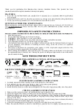
Thank  you  for  purchasing  this  Hampton  Bay  interior  chandelier  fixture.  This  product  has  been 
manufactured with the highest standards of safety and quality.  


FEATURES: 

1.


Uses  120  volt,  60  Watt  MAX  each,  standard  (A19)  incandescent  or  candelabra  (B10.5)  light  bulb(s) 
(not included). 

2.


Standard 96 in wire and 72 in chain for open entry-way, dining room, and cathedral ceiling installations. 

3.


Can be used with any standard, 120 volt, incandescent style dimmer switch. 


QUESTIONS, PROBLEMS, MISSING PARTS: 

Before returning to your local Home Depot, please call our Customer Service Team at 1-877-527-0313 or 
visit  www.homedepot.com.  Please  reference  SKU  518-132,  UPC  008938601863  or  SKU  526-920,  UPC 
008938601962. 


IMPORTANT SAFETY INSTRUCTIONS 

INSTALLATION INSTRUCTIONS PERTAINING TO RISK OF FIRE OR INJURY TO PERSONS 

1.


Read all instructions. 

2.


Do not install this lighting system in wet locations. 

3.


CAUTION 

- When the light is on, the lamp is HOT! 

4.


CAUTION 

- Hot surface. Keep away from curtains and other combustible materials. 

5.


Turn off/unplug and allow to cool before replacing bulb (lamp). 

6.


All electrical connections must be in accordance with local codes and the National Electrical Code. If 
you  are  unfamiliar  with  methods  of  installing  electrical  wiring,  secure  the  services  of  a  qualified 
licensed electrician. 

7.


This  fixture is  intended to be mounted to a 4in. square x 2-1/8in. deep  metal octagon outlet box. The 
box must be directly supported by the building structure. 

8.


Before starting the installation, disconnect the power by turning off the circuit breaker or by removing 
the appropriate  fuse  at  the  fuse  box.  Turning  the  power off  using  the  light  switch  is  not sufficient  to 
prevent electrical shock. 

SAVE THESE INSTRUCTIONS 


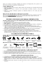
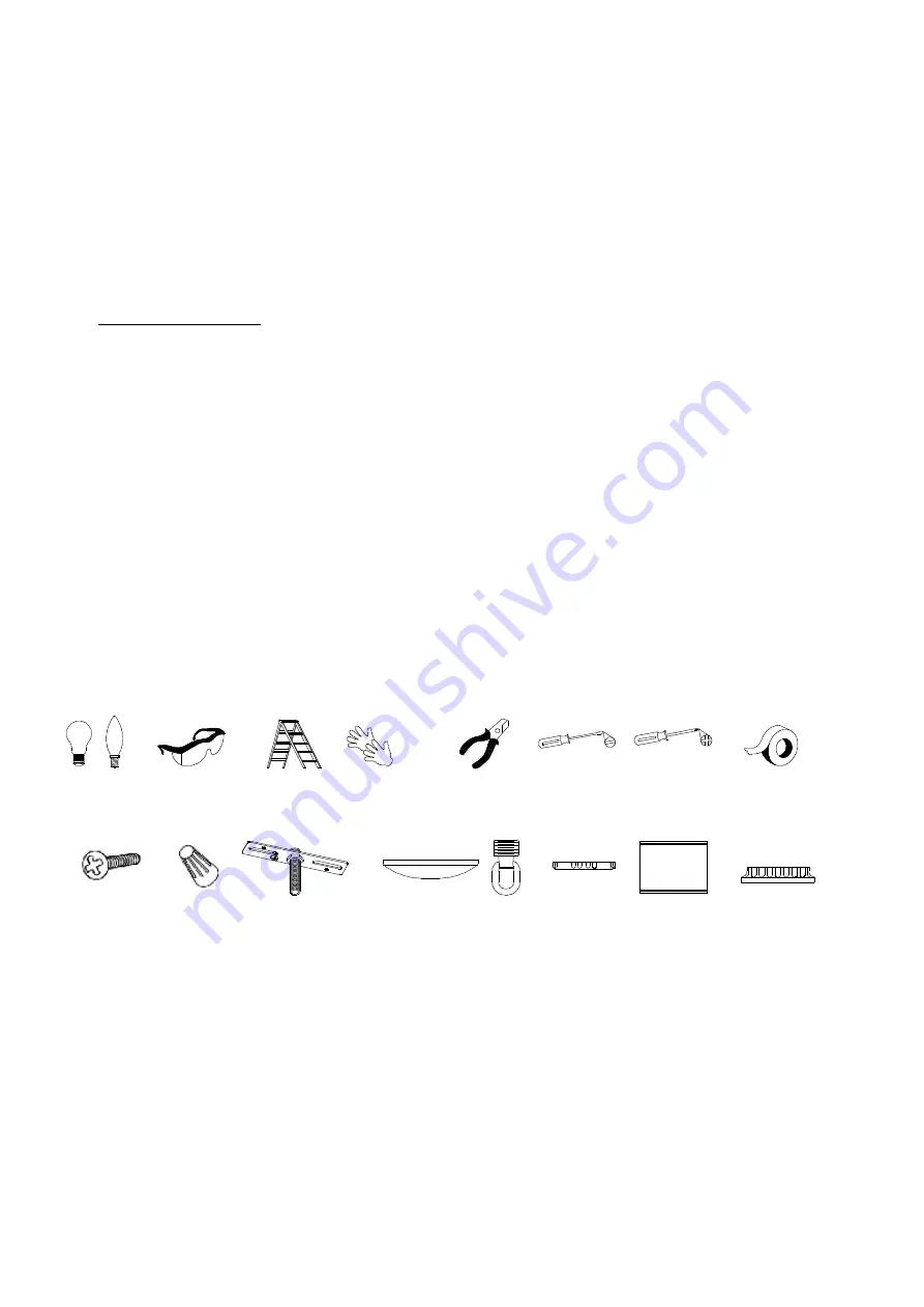
TOOLS REQUIRED FOR ASSEMBLY & INSTALLATION (not included):


 Bulb    Safety Goggles      Ladder       Gloves       Wire Strippers      Flathead       Phillips         Electrical tape                

                                                                                                               Screwdriver     Screwdriver                                                                                                                                                        


PARTS INCLUDED FOR ASSEMBLY (parts are not to scale):


(2)Outlet Box   (3)Wire            Mounting          Ceiling         Canopy   Loop ring     Fabric shade      Socket ring


Screws         Connectors     bracket assembly


canopy


loop


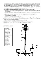
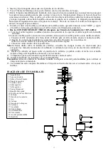
FIXTURE BODY ASSEMBLY INSTRUCTIONS 

1.


Carefully unpack the fixture and lay out all of the parts on a clean surface. 

2.


First distribute the bent tubes from fixture to three or five parts equal separately. 

3.


Secure the column into the coupler and tighten in place.      

4.


Install the fabric shade on to the socket and tighten with the socket ring (preassembly on to the socket).  


CEILING ASSEMBLY INSTRUCTIONS 

1.


Make sure the electrical is power off, pull leads down out of junction box. 

2.


Adjust the length of the chain according to the desired height by removing unnecessary links. 

3.


Thread  the  fixture  wire  and  the  ground  (bare)  wire  through  the  chain,  feeding  it  through  alternating 
links, then through  the canopy  loop. Loosen the  loop ring on the canopy  loop and allow ring  to  slide 
down over the chain. 

4.


Slide the canopy over the canopy loop and the chain (leave ring and canopy loose on chain at this time).  

5.


Insert and secure the threaded nipple into the canopy loop. 

6.   Attach the mounting strap to the outlet box using the two outlet box screws provided. 
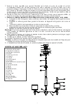
7. Raise the assembled  fixture to allow for installation to junction box (it is highly recommended to use a 

Summary of Contents for 518-132

Page 1: ...1 INSTRUCTION MANUAL CHANDELIER FIXTURE Brushed Nickel Finish Chrome Finish Home Depot SKU 518 132 UPC 008938601863 Home Depot SKU 526 920 UPC 008938601962...

Page 2: ...power by turning off the circuit breaker or by removing the appropriate fuse at the fuse box Turning the power off using the light switch is not sufficient to prevent electrical shock SAVE THESE INSTR...

Page 3: ...from the Outlet Box d Secure the connections using the wire connectors Wrap the wire connections with electrical tape to secure the connections e Position the wires back inside the outlet box Note If...

Page 4: ...ons neglect or mishandling This warranty shall not apply to any product that is found to have been improperly installed set up or used in any way not in accordance with the instructions supplied with...

Page 5: ...5 ANUAL D INSTRUCTIONS UMINAIRE LUSTRE Fini en nickel bross Fini chrome Home Depot UGS 518 132 CUP 008938601863 Home Depot UGS 526 920 CUP 008938601962...

Page 6: ...ement support e par la structure du b timent 8 Avant d entamer l installation d brancher l alimentation lectrique en fermant le disjoncteur ou en retirant le fusible appropri dans la bo te fusibles Co...

Page 7: ...s connexions l aide des capuchons de connexion Recouvrir les capuchons de connexion de ruban isolant pour obtenir des connexions plus s curitaires e Replacer les fils dans la bo te de sortie de couran...

Page 8: ...applique pas un produit qui est d clar avoir t mal install pos ou utilis d une fa on non conforme aux instructions qui l accompagnent Cette garantie ne s applique pas un d faut du produit qui d coule...

Page 9: ...9 MANUAL DE INSTRUCCIONES L MPARA CANDELABRO Acabado en N quel Cepillado Acabado en Cromo Home Depot SKU 518 132 UPC 008938601863 Home Depot SKU 526 920 UPC 008938601962...

Page 10: ...ofundidad y 10 16 cm2 La caja debe estar directamente apoyada en la estructura de la vivienda 8 Antes de empezar la instalaci n corta el suministro de electricidad apagando el cortacircuitos o retiran...

Page 11: ...el fixture para el cable de tierra desde el cuadro de salida d Asegura las conexiones mediante los conectores de cable Envuelve las conexiones de cable con cinta de electricista para lograr una conexi...

Page 12: ...t a no cubre ning n producto instalado configurado o usado incorrectamente sin seguir las instrucciones adjuntas al producto Esta garant a no cubre fallas del producto como consecuencia de un accident...

Reviews: