background image


3

second  person  to  help  support  the  weight  of  the  fixture  from  below  while  the  wiring  connections  are 
being  made).  Feed  the  wire  and  ground  wire  through  the  hole  in  the  center  of  the  mounting  strap  and 
rotate the threaded  nipple,  canopy  loop  and  preassembled  fixture clockwise  until  the  threaded  nipple  is 
secure  in the  mounting  strap.  Make  sure the  fixture  cable and  ground  wires  are  not twisted  during  this 
process.  

8.  Wrap  the  ground  wire  under  and  around  the  ground  screw  which  is  marked 

GND

,  and  fasten  the 

ground screw to make sure the ground wire is securely connected. 

9. 

Make the ELECTRICAL CONNECTIONS (Required Supply Circuit: 120V, 60Hz): 

a.


Connect the  negative  (raised  ribs  without writing)  wire  from  the  fixture  to the  negative  wire  from 
the Outlet Box.  

b.


Connect  the  positive  (smooth  with  writing)  wire  from  the  fixture  to  the  positive  wire  from  the 
Outlet Box.  

c.


Connect the ground (bare) wire from the fixture to the ground wire from the Outlet Box. 

d.


Secure the connections using the wire connectors. Wrap the wire connections with electrical    
tape to secure the connections.  

e.


Position the wires back inside the outlet box. 

Note:

 If you have electrical questions, consult your local  electrical  code for approved grounding  methods 

or obtain the services of a qualified, licensed electrician. 

 10.  Slide  the  canopy  back  over  the  canopy  loop  and  tighten  to  ceiling  using  the  loop  ring  (Adjust  the 

length of the threaded nipple if necessary).


11.   Check to make sure the canopy is held firmly against the ceiling.  

12.  Screw the bulb (not included) into the lamp-socket. 

Caution

: Refer to the re-lamping label near the lamp holder for recommended wattage. 

13.  Installation is complete. Turn on the power at the circuit breaker or fuse box.  
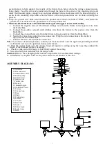
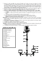
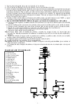


ASSEMBLY DIAGRAM:


1. Outlet Box 
2. Wire connector 
3. Ground (Bare) Wire 
4. Mounting strap 
5. Ground screw 
6. Negative wire 
7. Positive wire 
8. Hex nut 
9. Threaded nipple 
10. Outlet Box Screw 
11. Canopy 
12. Canopy loop 
13. Ring 
14. Chain 
15. Fixture loop  
16. Column 
17. Coupler 
18. Bent tube 
19. Socket 
20. Fabric shade 
21. Socket ring 
22. Bulb 

1

2

3
4

6

10

11

8
9

7

Summary of Contents for 518-132

Page 1: ...1 INSTRUCTION MANUAL CHANDELIER FIXTURE Brushed Nickel Finish Chrome Finish Home Depot SKU 518 132 UPC 008938601863 Home Depot SKU 526 920 UPC 008938601962...

Page 2: ...power by turning off the circuit breaker or by removing the appropriate fuse at the fuse box Turning the power off using the light switch is not sufficient to prevent electrical shock SAVE THESE INSTR...

Page 3: ...from the Outlet Box d Secure the connections using the wire connectors Wrap the wire connections with electrical tape to secure the connections e Position the wires back inside the outlet box Note If...

Page 4: ...ons neglect or mishandling This warranty shall not apply to any product that is found to have been improperly installed set up or used in any way not in accordance with the instructions supplied with...

Page 5: ...5 ANUAL D INSTRUCTIONS UMINAIRE LUSTRE Fini en nickel bross Fini chrome Home Depot UGS 518 132 CUP 008938601863 Home Depot UGS 526 920 CUP 008938601962...

Page 6: ...ement support e par la structure du b timent 8 Avant d entamer l installation d brancher l alimentation lectrique en fermant le disjoncteur ou en retirant le fusible appropri dans la bo te fusibles Co...

Page 7: ...s connexions l aide des capuchons de connexion Recouvrir les capuchons de connexion de ruban isolant pour obtenir des connexions plus s curitaires e Replacer les fils dans la bo te de sortie de couran...

Page 8: ...applique pas un produit qui est d clar avoir t mal install pos ou utilis d une fa on non conforme aux instructions qui l accompagnent Cette garantie ne s applique pas un d faut du produit qui d coule...

Page 9: ...9 MANUAL DE INSTRUCCIONES L MPARA CANDELABRO Acabado en N quel Cepillado Acabado en Cromo Home Depot SKU 518 132 UPC 008938601863 Home Depot SKU 526 920 UPC 008938601962...

Page 10: ...ofundidad y 10 16 cm2 La caja debe estar directamente apoyada en la estructura de la vivienda 8 Antes de empezar la instalaci n corta el suministro de electricidad apagando el cortacircuitos o retiran...

Page 11: ...el fixture para el cable de tierra desde el cuadro de salida d Asegura las conexiones mediante los conectores de cable Envuelve las conexiones de cable con cinta de electricista para lograr una conexi...

Page 12: ...t a no cubre ning n producto instalado configurado o usado incorrectamente sin seguir las instrucciones adjuntas al producto Esta garant a no cubre fallas del producto como consecuencia de un accident...

Reviews: