background image

6

Turn of the Century

TM

ASSEMBLY INSTRUCTIONS

8

7

6

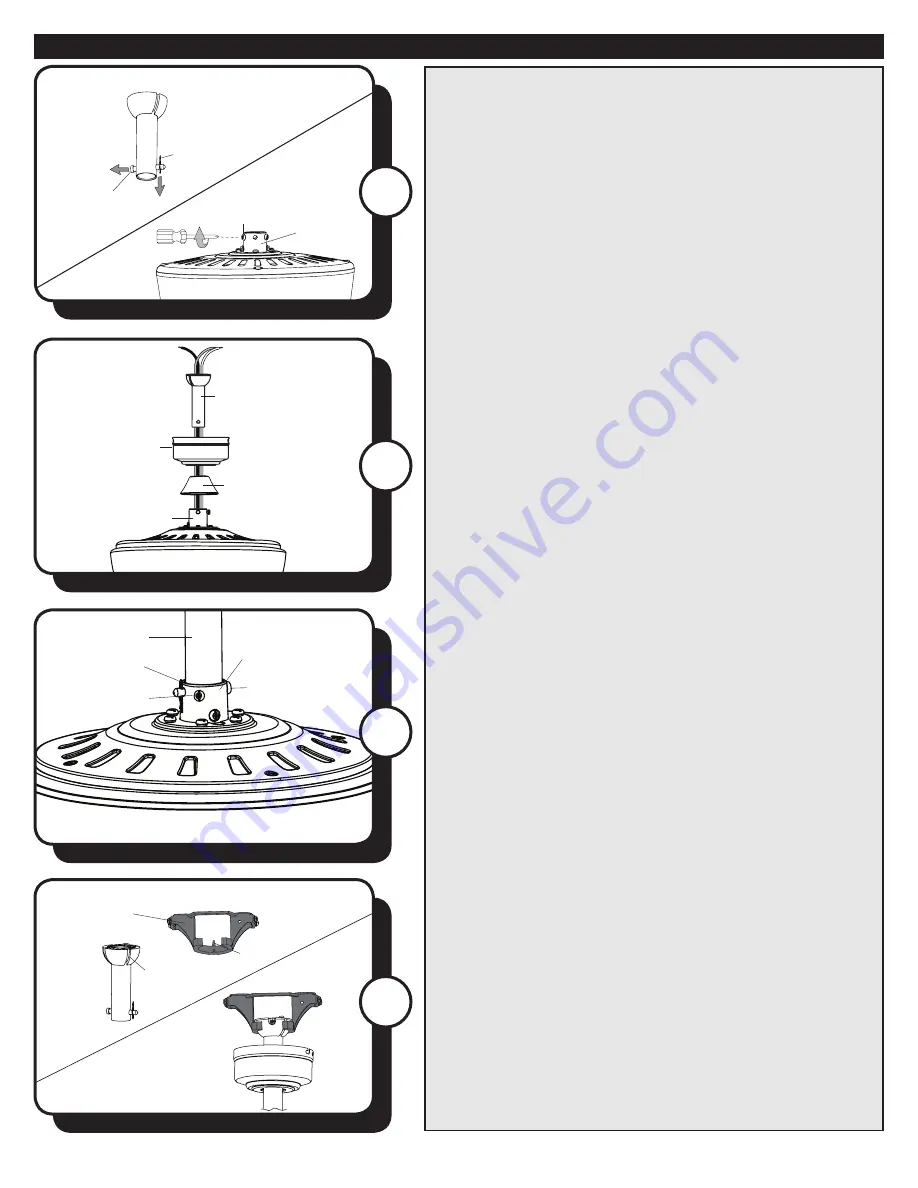
6.  Feed the wires coming from the yoke through the yoke 

cover, canopy and downrod.

7.  Insert the downrod into the yoke and reinstall the 

downrod pin and downrod clip. Then retighten the two  

set screws. 

Note:

  With wiring extending out of the downrod, 

measure 8 inches of lead wire and cut the excess wire 

with wire cutters (not included). Then strip 1/2” of 

insulation from the end of each wire. 

8.  Lift the downrod into the mounting bracket. Rotate the 

downrod until the tab in the mounting bracket is seated in 

the slot in the downrod ball.

WARNING: 

The fan and/or downrod should

not rotate in the mounting bracket if installed

correctly. Failure to align the slot in the downrod ball with 

the tab may result in fan falling causing serious injury or 

death.

Downrod

Canopy

Yoke Cover

Downrod Pin

Yoke

Downrod

Downrod Clip

Set Screw

Yoke

Tab

Slot

Downrod

Mounting 

Bracket

Downrod 

Clip

Set Screw

Yoke

Downrod

Pin

5. 

DOWNROD MOUNT

 - Remove the downrod pin and 

downrod clip from the downrod. Then, loosen but don’t 

remove the set screws in the yoke. 

5

Summary of Contents for 52" ELKTON

Page 1: ...CEILING FAN Owner s Manual Models 20595 TurnoftheCenturyTM 1 If a problem cannot be remedied or you are experiencing difficulty in installation please contact the Service Department 1 877 459 3267 9 a...

Page 2: ...Bracket Screw x 4 18 Downrod Clip 19 Downrod Pin 20 Motor Screw x 10 21 Fitter Plate Screws x 3 22 Set Screw x 2 23 Closemount Screw x 3 24 Blade Screw x 15 25 Blade Washer x 15 26 Wire Connector x 3...

Page 3: ...ount method is best suited for ceilings lower than 8 feet It does not utilize the downrod Downrod Mount is best suited for ceilings 8 ft or higher For taller ceilings you may want to use a longer down...

Page 4: ...ures Reorient or relocate the receiving antenna Increase the separation between the equipment and receiver Connect the equipment into and outlet on a circuit different from that to which the receiver...

Page 5: ...ting screws and washers provided with the outlet box 3 Remove all ten motor screws from the underside of the motor assembly Discard the plastic motor blocks but keep the motor screws for later 4 CLOSE...

Page 6: ...t the downrod into the mounting bracket Rotate the downrod until the tab in the mounting bracket is seated in the slot in the downrod ball WARNING The fan and or downrod should not rotate in the mount...

Page 7: ...t the black and blue wires from the fan to the black live hot supply wire Note If there is a second hot power wire coming from the outlet box connect it to the Blue light power fan wire for separate l...

Page 8: ...the light kit to the fitter plate using the three fitter plate screws 14 Remove the socket ring from the socket Lift the glass shade onto the socket and secure with socket ring Repeat for each socket...

Page 9: ...n fuse or circuit breaker 17 INSTALLATION WITHOUT LIGHT KIT OPTIONAL a Remove the three fitter plate screws from fitter plate b Install the switch housing cap to the bottom of the fitter plate with th...

Page 10: ...to stop before moving the reverse switch In warmer weather push the reverse switch left which will result in downward airflow creating a wind chill effect In cooler weather push the reverse switch ri...

Page 11: ...main power is turned off before entering switch housing 4 If using a light kit be sure the glass shades are finger tight Check to be sure light bulb are snug in sockets and not touching glass shade s...

Page 12: ...anty including but not limited to any implied warranty of merchantability or fitness for a particular purpose become void This warranty and any implied warranty including but not limited to any implie...

Reviews: