background image

2

Table of Contents ................................................................ 2
Safety Information ............................................................... 2
Warranty ............................................................................... 3
Pre-Installation .................................................................... 3
Installation ............................................................................ 6

Assembly .............................................................................. 7
Operation ........................................................................... 14
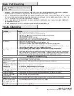
Care and Cleaning ............................................................. 17
Troubleshooting ................................................................. 17

1.

To reduce the risk of electric shock, ensure the electricity has been

turned off at the circuit breaker or fuse box before you begin.

2.

All wiring must be in accordance with the National Electrical Code

ANSI/NFPA 70 and local electrical codes. Electrical installation

should be performed by a qualified licensed electrician.

3. 

The outlet box and support structure must be securely mounted and

capable of reliably supporting 35 lbs. (15.9 kg). Use only UL Listed

outlet boxes marked “Acceptable for Fan Support of 35 lbs. (15.9 kg)

or less.”

4. 

The fan must be mounted with a minimum of 7 ft. (2.1 m) clearance

from the trailing edge of the blades to the floor.

5.

Do not operate the reversing switch while the fan blades are in

motion. You must turn the fan off and stop the blades before you

reverse the blade direction.

6.

Do not place objects in the path of the blades.

7.

To avoid personal injury or damage to the fan and other items, use

caution when working around or cleaning the fan.

8.

Electrical diagrams are for reference only. Light kits that are not

packed with the fan must be UL-listed and marked suitable for use

with the model fan you are installing. Switches must be UL General

Use Switches. Refer to the instructions packaged with the light kits

and switches for proper assembly.

9.

After making electrical connections, spliced conductors should be

turned upward and pushed carefully up into the outlet box. The

wires should be spread apart with the grounded conductor and the

equipment-grounding conductor on one side of the outlet box.

10.

All setscrews must be checked and retightened where

necessary before installation.

WARNING:

 To reduce the risk of personal injury,

do not bend the blade brackets (also referred to as

flanges) during assembly or after installation. Do not

insert objects in the path of the blades.

WARNING:

 Remove the rubber motor stops on

the bottom of the fan before installing the blades or

testing the motor.

WARNING:

 To reduce the risk of fire or electric

shock, do not use this fan with any solid-state speed

control device.

WARNING:

 To avoid possible electrical shock,

turn the electricity off at the main fuse box before

wiring. If you feel you do not have enough electrical

wiring knowledge or experience, contact a licensed 

electrician.

WARNING:

 Electrical diagrams are for reference

only. Optional use of any light kit shall be UL-listed

and marked suitable for use with this fan.

WARNING:

 To reduce the risk of fire, electric shock, 

or personal injury, mount to outlet box marked 

“Acceptable for fan support of 35 lbs. (15.9 kg) or 

less,” and use the screws provided with the outlet 

box.

Safety Information

Table of Contents

READ AND SAVE THESE INSTRUCTIONS

WARNING:

 To reduce the risk of fire or electric 

shock, this fan should only be used with fan speed 

control part no. MR225A, manufactured by Chungear 

Industrial Co., Ltd.

WARNING:

 To reduce the risk of electric shock, this 

fan must be installed with an isolating wall switch.

FCC Statement:

 This equipment has been tested and found to comply with the limits for a Class B digital device, pursuant to Part 15 of the FCC Rules. These limits are designed to provide 

reasonable protection against harmful interference in a residential installation. This equipment generates, uses and can radiate radio frequency energy and, if not installed and used in 
accordance with the instructions, may cause harmful interference to radio communications. However, there is no guarantee that interference will not occur in a particular installation. If 
this equipment does cause harmful interference to radio or television reception, which can be determined by turning the equipment off and on, the user is encouraged to try to correct the 
interference by one or more of the following measures:


Reorient or relocate the receiving antenna.


Increase the separation between the equipment and receiver.


Connect the equipment into an outlet on a circuit different from that to which the receiver is connected.


Consult the dealer or an experienced radio/TV technician for help.

CAUTION

:

Any changes or modifications not expressly approved by the grantee of this device could void the user’s authority to operate the equipment.
The distance between user and products should be no less than 20 cm.

This device complies with Part 15 of the FCC rules. Operation is subject to the following two conditions: 1) this device may not cause harmful interference, and 2) this device must accept any interference received, including interference that 

may cause undesired operation.

Summary of Contents for 52-LASO

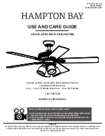
Page 1: ...ay Item xxxx xxx xxx Model 56058 UL Model 52 LASO To view an instructional video on how to install this product 1 Go to www homedepot com and enter either the Item or Model number found in the top right corner of the cover of this instruction manual in the search field 2 Click on your product from the list of search results and click on the video link in the Product Overview section Questions prob...

Page 2: ...e electrical shock turn the electricity off at the main fuse box before wiring If you feel you do not have enough electrical wiring knowledge or experience contact a licensed electrician WARNING Electrical diagrams are for reference only Optional use of any light kit shall be UL listed and marked suitable for use with this fan WARNING To reduce the risk of fire electric shock or personal injury mo...

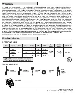
Page 3: ...our responsibility Damage to any part such as by accident misuse improper installation or by affixing any accessories is not covered by this warranty Because of varying climatic conditions this warranty does not cover any changes in brass finish including rusting pitting corroding tarnishing or peeling Brass finishes of this type give their longest useful life when protected from varying weather c...

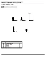
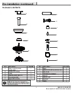
Page 4: ... Quantity AA Extra blade bracket screw 1 BB Plastic wire connector 3 CC Hanger pin 1 DD Locking pin 1 EE Blade screws 16 Pre Installation continued HARDWARE INCLUDED NOTE Hardware not shown to actual size BB CC DD AA EE ...

Page 5: ...tter assembly 1 Part Description Quantity G Blade 5 H Blade bracket with pre installed screws 5 I Glass shade 4 J LED bulbs 9 5w Maximum 4 K Receiver 1 L Remote control 1 M Lead wire 1 N Battery 2 IMPORTANT This product and or components are governed by one or more of the following U S Patents 5 947 436 5 988 580 6 010 110 6 046 416 6 210 117 and other patents pending Pre Installation continued PA...

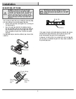
Page 6: ...the appropriate fasteners and materials The outlet box and its bracing must be able to fully support the weight of the moving fan at least 35 lbs Do not use a plastic outlet box The illustrations below show three different ways to mount the outlet box If the canopy C touches the ball downrod assembly B then remove the decorative canopy bottom cover and turn the canopy C 180 before attaching the ca...

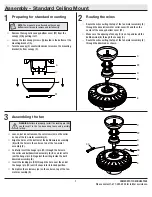
Page 7: ...ghten the setscrews JJ on the collar on top of the fan motor assembly E 2 3 1 WARNING Failure to properly install the locking pin DD could result in the fan becoming loose and possibly falling Remove the magnetic canopy bottom cover FF from the canopy C by pulling it off Loosen the two canopy screws II located in the bottom of the mounting bracket A Turn the canopy C counterclockwise to remove the...

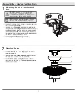
Page 8: ...urely tighten the two mounting screws LL 1 WARNING To reduce the risk of fire electric shock or personal injury mount to an outlet box marked Acceptable for fan support of 35 lbs 15 9 kg or less and use the screws provided with the outlet box Hanging the fan 2 Carefully lift the fan motor assembly E up to the slide on mounting bracket A Insert the ball portion of the ball downrod assembly B into t...

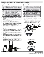
Page 9: ... remote control has already been paired to the ceiling fan for your convenience If you have two of the same model fans in your home please follow the steps below to control each fan independently NOTE The remote control battery will weaken with age and should be replaced before leaking takes place as this will damage the remote control Dispose of used battery properly and keep the battery out of t...

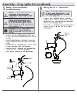
Page 10: ... fan wiring consult an electrician for the proper size wire nuts to use IMPORTANT Use the wire connecting nuts BB supplied with your fan Secure the connectors with electrical tape and ensure there are no loose strands or connections Spread the wires apart so that the green and white wires are on one side of the outlet box and the black wire is on the other side Connect the green fan wires to the h...

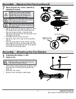
Page 11: ...the groove could cause damage to the wiring NOTE The magnet is pre attached on the canopy bottom cover for you to remove and install easily Align the locking slots of the canopy C with the two screws HH and alignment post KK in the mounting bracket A Push up the canopy C and turn it clockwise until the alignment post KK engages to the round hole and the screws HH engage to the key slots Firmly tig...

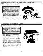
Page 12: ...the three holes in the switch cup cover of the light kit fitter assembly F with the three holes in the switch cup of the fan motor assembly E Make sure the notch in the switch cup cover of the light kit fitter assembly F clears the reversing switch in the switch cup of the fan motor assembly E Position the light kit fitter assembly F and re install the three screws VV that were removed in first st...

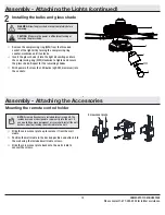
Page 13: ...TION Make sure the power is off before attaching or removing the glass shade WARNING Allow the glass shade to cool completely before removing Assembly Attaching the Accessories Mounting the remote control holder Slide the screw cover plate up to remove it from the wall cradle Position the wall cradle in the desired position and attach it to the wall using the included wall cradle screws Slide the ...

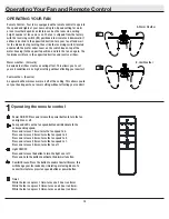
Page 14: ... allows you to set your heating unit on a lower setting without affecting your comfort OPERATING YOUR FAN A Warm Weather B Cool Weather Operating Your Fan and Remote Control 1Operating the remote control Power ON OFF Press and release the power button to turn the fan and light on or off Fan speed LEDs on the fan speed button will illuminate to the corresponding speed Press and release 1 time turns...

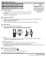
Page 15: ... to access the QR code for your light you can put it into discovery mode with the following sequence Switch the device off and on 5 times The light will pulse to show that it can now be discovered In the Hubspace app tap the plus sign in the upper right corner and follow the instructions to discover devices More than one device can be added at a time using this method Set up your voice assistant 4...

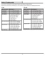
Page 16: ...me Alexa When you want to Ask Google to Turn on the fan only turn on device name fan power Turn off the fan only turn off device name fan power Turn on the light only turn on device name light power Turn off the light only turn off device name light power Change the brightness Set device name brightness to 75 Set device name light to 25 Brighten device name Dim device name Brighten room name Dim r...

Page 17: ...work may be down My device cannot find any Wi Fi networks Make sure you have a 2 4GHz capable Wi Fi network within range of the device you are trying to add My device is in a location that does not have Wi Fi Can I still use it with the Hubspace app Yes Use the app on a phone with an Internet connection like LTE The phone must be within Bluetooth range of your Hubspace device I cannot find the QR ...

Page 18: ... problems missing parts Before returning to the store call Hubspace Customer Service 8 a m 7 p m EST Monday Friday 9 a m 6 p m EST Saturday 1 877 592 5233 HOMEDEPOT COM HUBSPACE Retain this manual for future use ...

Reviews: