background image

8

Assembly - Hanging the Fan

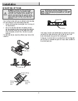
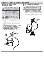
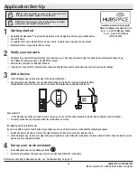
Attaching the fan to the electrical 
box


Pass the 120-Volt supply wires through the center hole in the 
slide-on mounting bracket (A).


Install the slide-on mounting bracket (A) on the outlet box by 
sliding the slide-on mounting bracket (A) over the two screws (LL) 
provided with the outlet box. If necessary, use leveling washers 
(not included) between the slide-on mounting bracket (A) and 
the outlet box. The flat side of the slide-on mounting bracket (A) 
should face toward the outlet box, as shown.


Securely tighten the two mounting screws (LL).

1

WARNING:

 To reduce the risk of fire, electric shock 

or personal injury, mount to an outlet box marked 

“Acceptable for fan support of 35 lbs. (15.9 kg) or less,” 

and use the screws provided with the outlet box.
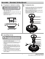
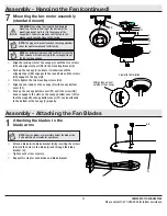
Hanging the fan

2


Carefully lift the fan-motor assembly (E) up to the slide-on 
mounting bracket (A).


Insert the ball portion of the ball/downrod assembly (B) into 
the socket of the slide-on mounting bracket (A).


Turn the ball/downrod assembly (B) clockwise until it is 
seated with the tab of the slide-on mounting bracket aligned 
with the slot in the ball.

NOTE:

 The mounting bracket (A) is designed to slide into 

place on an outlet box with the outlet box screws (LL).

LL

LL

A

A

C

D

E

FF

Summary of Contents for 52-LASO

Page 1: ...ay Item xxxx xxx xxx Model 56058 UL Model 52 LASO To view an instructional video on how to install this product 1 Go to www homedepot com and enter either the Item or Model number found in the top right corner of the cover of this instruction manual in the search field 2 Click on your product from the list of search results and click on the video link in the Product Overview section Questions prob...

Page 2: ...e electrical shock turn the electricity off at the main fuse box before wiring If you feel you do not have enough electrical wiring knowledge or experience contact a licensed electrician WARNING Electrical diagrams are for reference only Optional use of any light kit shall be UL listed and marked suitable for use with this fan WARNING To reduce the risk of fire electric shock or personal injury mo...

Page 3: ...our responsibility Damage to any part such as by accident misuse improper installation or by affixing any accessories is not covered by this warranty Because of varying climatic conditions this warranty does not cover any changes in brass finish including rusting pitting corroding tarnishing or peeling Brass finishes of this type give their longest useful life when protected from varying weather c...

Page 4: ... Quantity AA Extra blade bracket screw 1 BB Plastic wire connector 3 CC Hanger pin 1 DD Locking pin 1 EE Blade screws 16 Pre Installation continued HARDWARE INCLUDED NOTE Hardware not shown to actual size BB CC DD AA EE ...

Page 5: ...tter assembly 1 Part Description Quantity G Blade 5 H Blade bracket with pre installed screws 5 I Glass shade 4 J LED bulbs 9 5w Maximum 4 K Receiver 1 L Remote control 1 M Lead wire 1 N Battery 2 IMPORTANT This product and or components are governed by one or more of the following U S Patents 5 947 436 5 988 580 6 010 110 6 046 416 6 210 117 and other patents pending Pre Installation continued PA...

Page 6: ...the appropriate fasteners and materials The outlet box and its bracing must be able to fully support the weight of the moving fan at least 35 lbs Do not use a plastic outlet box The illustrations below show three different ways to mount the outlet box If the canopy C touches the ball downrod assembly B then remove the decorative canopy bottom cover and turn the canopy C 180 before attaching the ca...

Page 7: ...ghten the setscrews JJ on the collar on top of the fan motor assembly E 2 3 1 WARNING Failure to properly install the locking pin DD could result in the fan becoming loose and possibly falling Remove the magnetic canopy bottom cover FF from the canopy C by pulling it off Loosen the two canopy screws II located in the bottom of the mounting bracket A Turn the canopy C counterclockwise to remove the...

Page 8: ...urely tighten the two mounting screws LL 1 WARNING To reduce the risk of fire electric shock or personal injury mount to an outlet box marked Acceptable for fan support of 35 lbs 15 9 kg or less and use the screws provided with the outlet box Hanging the fan 2 Carefully lift the fan motor assembly E up to the slide on mounting bracket A Insert the ball portion of the ball downrod assembly B into t...

Page 9: ... remote control has already been paired to the ceiling fan for your convenience If you have two of the same model fans in your home please follow the steps below to control each fan independently NOTE The remote control battery will weaken with age and should be replaced before leaking takes place as this will damage the remote control Dispose of used battery properly and keep the battery out of t...

Page 10: ... fan wiring consult an electrician for the proper size wire nuts to use IMPORTANT Use the wire connecting nuts BB supplied with your fan Secure the connectors with electrical tape and ensure there are no loose strands or connections Spread the wires apart so that the green and white wires are on one side of the outlet box and the black wire is on the other side Connect the green fan wires to the h...

Page 11: ...the groove could cause damage to the wiring NOTE The magnet is pre attached on the canopy bottom cover for you to remove and install easily Align the locking slots of the canopy C with the two screws HH and alignment post KK in the mounting bracket A Push up the canopy C and turn it clockwise until the alignment post KK engages to the round hole and the screws HH engage to the key slots Firmly tig...

Page 12: ...the three holes in the switch cup cover of the light kit fitter assembly F with the three holes in the switch cup of the fan motor assembly E Make sure the notch in the switch cup cover of the light kit fitter assembly F clears the reversing switch in the switch cup of the fan motor assembly E Position the light kit fitter assembly F and re install the three screws VV that were removed in first st...

Page 13: ...TION Make sure the power is off before attaching or removing the glass shade WARNING Allow the glass shade to cool completely before removing Assembly Attaching the Accessories Mounting the remote control holder Slide the screw cover plate up to remove it from the wall cradle Position the wall cradle in the desired position and attach it to the wall using the included wall cradle screws Slide the ...

Page 14: ... allows you to set your heating unit on a lower setting without affecting your comfort OPERATING YOUR FAN A Warm Weather B Cool Weather Operating Your Fan and Remote Control 1Operating the remote control Power ON OFF Press and release the power button to turn the fan and light on or off Fan speed LEDs on the fan speed button will illuminate to the corresponding speed Press and release 1 time turns...

Page 15: ... to access the QR code for your light you can put it into discovery mode with the following sequence Switch the device off and on 5 times The light will pulse to show that it can now be discovered In the Hubspace app tap the plus sign in the upper right corner and follow the instructions to discover devices More than one device can be added at a time using this method Set up your voice assistant 4...

Page 16: ...me Alexa When you want to Ask Google to Turn on the fan only turn on device name fan power Turn off the fan only turn off device name fan power Turn on the light only turn on device name light power Turn off the light only turn off device name light power Change the brightness Set device name brightness to 75 Set device name light to 25 Brighten device name Dim device name Brighten room name Dim r...

Page 17: ...work may be down My device cannot find any Wi Fi networks Make sure you have a 2 4GHz capable Wi Fi network within range of the device you are trying to add My device is in a location that does not have Wi Fi Can I still use it with the Hubspace app Yes Use the app on a phone with an Internet connection like LTE The phone must be within Bluetooth range of your Hubspace device I cannot find the QR ...

Page 18: ... problems missing parts Before returning to the store call Hubspace Customer Service 8 a m 7 p m EST Monday Friday 9 a m 6 p m EST Saturday 1 877 592 5233 HOMEDEPOT COM HUBSPACE Retain this manual for future use ...

Reviews: