background image

80213


2

R44038


Table


of


Contents


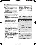
Table of Contents

2


Safety Information

2


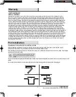
Warranty

3


Pre-Installation

3

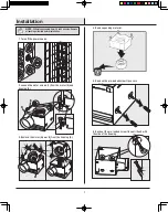
Installation

7


Safety


Information


1

.

This ventilation fan is approved for use over a bathtub or 
when


installed in a GFCI protected circuit. Do not use unapproved 

fans over a bathtub or shower that does not


include a GFCI 

protected circuit

shower


2

.

Installation work must be carried out by a qualified 
accordance with all local and safety codes including the rules for 
fire-rated construction

.

person(s) in 


3

.

To reduce the risk of fi
compliance with local codes. Do not vent exhaust air into spaces 
within walls, ceilings, attics, crawl spaces, or garages

.


re, always vent fans to the  exterior and in 


4

.

Install ductwork in a straight line with minimal  bends

.


5

.

Use


120V

60Hz


for


the


electrical 

unit. Follow all local safety and electrical


codes.


supply and


properly ground the 


6

.

Do not use this fan with any solid state control 
dimmer switch. Solid-state controls may cause harmonic 
distortion, which can cause a motor humming noise

.


device; such as a 


8

.

Suf
exhausting


of


gases


through


the


flue (chimney) of fuel 

burning equipment


to prevent back drafting. Follow the heating 

equipment manufacturer’s guideline and safety standards such 
as those published by the National Fire Protection Association 
(NFPA), and the American Society for Heating, Refrigeration and 
Air Conditioning Engineers (ASHRAE),


and the local code 

authorities.

ficient


air is needed


for


proper


combustion


and


Planning


For


Successful


Installation

3


Installation


Options

4


Tools Required

5


Materials


Required

5


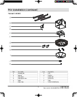
Hardware Included

5


Package


Contents

6


Specifications

23


Service


Parts

24


7

.

To reduce the risk of fire, electric shock or injury to persons, 
observe the following

:


Use this unit only


in the manner intended by 

If you have questions, contact the manufacturer

.

the manufacturer

o

Before servicing or cleaning the unit, switch the power 

the service panel and lock the service disconnecting means to 
prevent power from being switched on accidentally. When the 
service disconnecting means cannot be locked, securely 
fasten a prominent warning device, such as a tag, to the 
service panel

.

off at 

o

NO

the discharge

Do


not


reduce

Reducing


the


duct


size


can 

increase fan noise

.

TE

Make


sure


the


duct


work


size


is


a


minimum


of


NO

fan


body


to


minimize


building


heat


loss


and


gain

TE

Proper installation of insulation around


and over 


WARNING

INSTALLATIONS ONLY.

FOR USE IN NON FIRE-RELATED 

WARNING

DWELLINGS


ONLY. 

FOR  USE IN ONE-AND-TWO FAMILY


WARNING

not


use


this


fan


with


any


solid-state


speed


control


device

To reduce the risk of fire or electric shock

do


CAUTION

temperature


will


exceed


104ºF (40ºC).

Do not install in locations where the air 


CAUTION

exhaust hazardous


or explosive materials


and vapors

.

For general


ventilating


use only

Do not


use to 


IMPORTANT

professional electrician  regarding the


wiring of your 

ventilation


fan

.

You may want to consult with a 


WARNING

areas


where


hazardous or explosive


vapors are


present

.

Not suitable for


use as a range hood or in 


WARNING

outdoors. Never place a switch where it can be reached from 
a tub or shower. Install the fan at least 5 ft. (1.52 m) above 
the floor.

Ducted fans must always be vented to the 

PLEASE READ AND SAVE THESE INSTRUCTIONS.

9

.

When cutting or drilling into wall(s) or ceiling, do not damage 
electrical wiring or other hidden utilities.

10

.

This unit must be grounded.

This unit must not be installed in a ceiling thermally insulated to 

a value greater than R40.

11

.

Do not install fan above or inside a 45-degree angle projected 

outwards from the cooking equipment element closest to the 

fan. See instruction sheet for clarification.

12

.

Troubleshootings

23


A. New Construction - Attaching to Joist
B. New Construction - Suspended between Joist
C. Existing Construction - Accessible from Above
D. Existing Construction - Accessible from Below 
E. Attaching the Grill

9

11

15
19

21

Care and


Cleaning

23


Summary of Contents for 80213

Page 1: ...r home Visit us online to see our full line of products available for your home improvement needs Thank you for choosing Hampton Bay USE AND CARE GUIDE Questions problems missing parts Before returnin...

Page 2: ...servicing or cleaning the unit switch the power the service panel and lock the service disconnecting means to prevent power from being switched on accidentally When the service disconnecting means ca...

Page 3: ...n warranty service you must present a copy of the receipt as proof of purchase All costs of removing and reinstalling the product are your responsibility Damage to any part such as by accident or misu...

Page 4: ...ing opening are multiple installation configurations possible for this ventilation fan Not all configurations are shown If your installation requires CAUTION To avoid motor bearing damage and noisy un...

Page 5: ...Drill Slotted screwdriver Saw Ruler Pencil Wrench Duct vent Duct clamp Duct tape Duct piping MATERIALS REQUIRED NOTE Hardware not shown to actual size HARDWARE INCLUDED Part Description Quantity AA 4...

Page 6: ...urther assistance Pre installation continued Part Description A Mounting Rail B Housing C Wiring Cover D E Motor PACKAGE CONTENTS A B C D E F G H I J K Part Description G H Grill Nut I Glass Dome J Do...

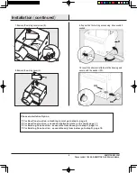
Page 7: ...tes Remove F 1 Turn off the power source 2 Loosen the motor screws F from the motor E and housing B 3 Remove the motor blower E from the housing B 4 Remove packing material 6 Back out the pre loaded s...

Page 8: ...9 For New Construction suspended between joists go to step B page 11 For Existing Construction accessible from above go to step C page 15 For Existing Construction accessible only from below go to st...

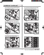
Page 9: ...ST B AA A11 Position the correct depth mark at the bottom ge of the joist based on the thickness of your sheetrock ed A13 Route wires through the strain relief A12 Screw pre loaded screws into the joi...

Page 10: ...ing cover C A18 Reinstall the motor E by inserting the tabs and pushing up into position Make sure the wires are not pinched between the motor and the housing A16 Connect 4 duct and vent to the outsid...

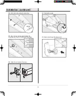
Page 11: ...or If the motor does not run check the plug connection B11 Slide the mounting rails A into the brackets on the housing B B12 Position the correct depth mark at the bottom edge of the joist based on th...

Page 12: ...a hole in the center of each outline B17 Tighten the screws B15 Insert screws leaving space between the screw head and the joist Screws are not provided B18 Route wires through the strain relief B16...

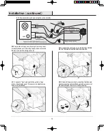
Page 13: ...box or under the wiring cover C B22 Connect the wiring harness DO NOT ALLOW THE MOTOR TO HANG FROM THE WIRING HARNESS B21 Connect 4 duct and vent to the outside Tape joints If ducting does not fit se...

Page 14: ...4 1 Installation continued 21 B24 Secure the motor by tightening the two screws F B25 Turn on the power source B26 Test the motor If the motor does not run check the plug connection F...

Page 15: ...ng is large enough to accommodate the new motor housing 8 x8 1 2 Use the motor housing as a template to mark position Cut out an opening for the housing C12 Slide the mounting rails A onto the bracket...

Page 16: ...ails A onto the screws C15 Drill a hole in the center of each outline C18 Tighten the screws C16 Insert screws leaving space between the screw head and joist Screws are not provided C19 Connect 4 duct...

Page 17: ...relief screws C22 Connect wires as shown using the wire nuts AA C23 Install the wiring cover C using the wiring cover screw D Make sure all wiring connections are inside the box or under the wiring c...

Page 18: ...g the tabs and pushing up into position Make sure the wires are not pinched between the motor and the housing C28 Test the motor If the motor does not run check the plug connection C26 Secure the moto...

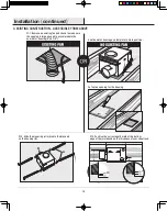
Page 19: ...he new motor housing 8 x8 1 2 D14 Attach existing ducting to duct connector Tape joints If ducting does not fit securely an adapter may need to be purchased D12 Move the housing B into position above...

Page 20: ...wiring connections are inside the box or under the wiring cover C D19 Reinstall the motor E by inserting the tabs and pushing up into position Make sure the wires are not pinched between the motor an...

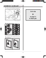
Page 21: ...does not run check the plug connection E1 Remove the grill nuts H from the housing B E2 Connect the wiring harness DO NOT ALLOW THE FIXTURE TO HANG FROM THE WIRING HARNESS E3 Align posts A B C and D...

Page 22: ...ill nuts MUST be properly installed E4 Attach the grill nuts H E7 Secure the glass dome I into position against the fixture using the dome cover J and finial K E5 Install the LED bulbs L E6 Align the...

Page 23: ...80213 Air direction 80 cfm Voltage 120 V Hertz 60 Hz Duct diameter 4 in 10 16 cm Noise 2 0 Sone Power consumption watts 23 W Speed 1250 rpm Air deliver at 0 1 WG 80 cfm Weight 11 9 lbs 5 4 kg Problem...

Page 24: ...ance Service Parts Part Number If you need parts or service assistance please call 1 855 HD HAMPTON or visit us at our web site at http www HAMPTONBAY com 95044 01 000 95029 01 000 77481 01 000 03242...

Page 25: ...ton Bay Customer Service 1 855 HD HAMPTON HAMPTONBAY COM Questions problems missing parts Before returning to the store 8 a m 7 p m EST Monday Friday 9 a m 6 p m EST Saturday Retain this manual for fu...

Reviews: