background image

12

Assembly - Attaching the Light Kit

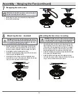
Attaching the light kit fitter
assembly

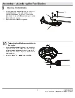
Installing the glass shades 
and bulbs

11

12


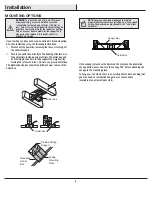
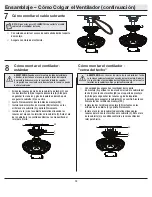
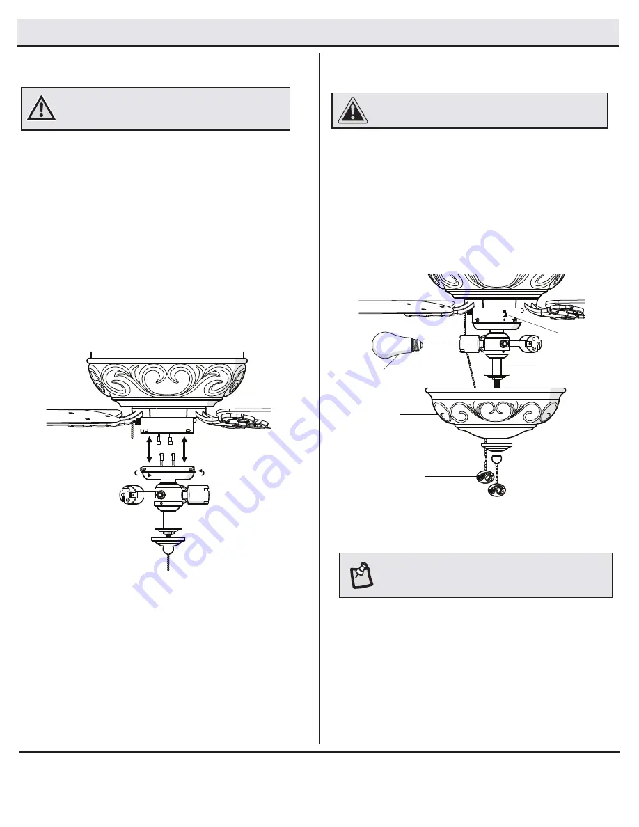
Loosen the three screws on the switch cup cover of the 
light kit fitter assembly (E).


Connect the to the light kit fitter assembly (E) to the 
wires from the switch cup of the fan motor assembly (D) 
by connecting the molded adapter plugs together (blue 
to black, white to white). Carefully tuck all wires and 
splices into the switch cup.


Align the three screws on the switch cup cover of the 
light kit fitter assembly (E) with the three key slots in the 
switch cup. Make sure the notch in the switch cup cover 
of the light kit fitter assembly clears the reverse switch 
in the switch cup. Position the light kit fitter assembly 
(E) on the switch cup and turn clockwise until it locks. 
Tighten the three screws that were loosened in the first 
step to secure the light kit fitter assembly (E).


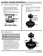
Remove the bottom cover and the finial from the light kit 
fitter (E).


With power off, install the three LED bulbs (J) by twisting 
them into the light bulb sockets.


Position the glass bowl (I) and the bottom cover over the 
threaded nipple and pass the fan switch chain through 
the offset hole in the bottom cover.


Re-install the finial.

WARNING:

 To reduce the risk of electric shock, disconnect 

the electrical supply circuit to the fan before installing the 

light fixture.

D

E

I

J

FF

E

RR

NOTE:

 Notice the location of the fan’s reverse switch (RR). 

This is the switch used to change the fan’s directional 

rotation. For more information on the operation of this switch, 

see Operating Your Fan on page 13.

CAUTION:

 Make sure the fan switch chain does not make 

contact with the light bulbs.

Summary of Contents for 91171

Page 1: ...s ceiling fan We strive to continually create quality products designed to enhance your home Visit us online to see our full line of products available for your home improvement needs Thank you for ch...

Page 2: ...trical connections spliced conductors should be turned upward and pushed carefully up into the outlet box The wires should be spread apart with the grounded conductor and the equipment grounding condu...

Page 3: ...shall render the warranty invalid There is no other express warranty Hampton Bay hereby disclaims any and all warranties including but not limited to those of merchantability and fitness for a particu...

Page 4: ...g pin 1 Part Description Quantity EE Extra plastic plug to be used for fan wothout light kit 1 FF Pull chain 2 GG Extra blade bracket screw and lockwasher 1 HH Close to ceiling mount hardware rubber g...

Page 5: ...ight kit fitter assembly 1 Part Description Quantity F Decorative motor collar cover 1 G Blade 5 H Blade bracket flange screws pre installed 5 I Glass bowl 1 J LED Light bulb 9 5 Watt maximum 3 IMPORT...

Page 6: ...Use the appropriate fasteners and materials The outlet box and its bracing must be able to fully support the weight of the moving fan at least 35 lbs Do not use a plastic outlet box The illustrations...

Page 7: ...he collar M on top of the motor housing D Remove the canopy ring KK from the canopy C by turning the ring counter clockwise until it unlocks Remove the mounting bracket A from the canopy C by loosenin...

Page 8: ...e fan motor housing D Route the wires exiting the top of the fan motor assembly D through the rubber gasket HH canopy ring KK and ceiling canopy C make sure the slot openings are on top place the rubb...

Page 9: ...the lead wire to your desired length no shorter than 12in This will make extra room in the canopy C if you do not wish to cut the wires you will need to neatly wrap them Connect the fan motor green wi...

Page 10: ...The locking slots of the ceiling canopy are provided only as an aid to mounting Do not leave the fan assembly unattended until all four canopy screws are engaged and firmly tightened SS A C L Careful...

Page 11: ...ached to the blade bracket H Insert a screw into the blade bracket H Repeat for the two remaining screws AA Tighten each screw securely Repeat these steps for the remaining blades Fasten the blade ass...

Page 12: ...bly E on the switch cup and turn clockwise until it locks Tighten the three screws that were loosened in the first step to secure the light kit fitter assembly E Remove the bottom cover and the finial...

Page 13: ...ting your comfort NOTE Wait for the fan to stop before reversing the direction of blade rotation WARNING To reduce the risk personal injury Do not bend the blade holders while installing balancing the...

Page 14: ...ove the tip of one of the blades Measure from a point on the center of the blade to the point on the ceiling Rotate the fan until the next blade is positioned for measurement and measure from the same...

Page 15: ...Questions problems missing parts Before returning to the store call Hampton Bay Customer Service 8 a m 6 p m EST Monday Friday 1 855 HD HAMPTON HAMPTONBAY COM Retain this manual for future use...

Page 16: ...Nos esforzamos para continuamente crear produc tos de calidad dise ados para mejorar su hogar Vis tenos en Internet para ver nuestra l nea completa de productos disponibles para las necesidades de mej...

Page 17: ...almados hacia arriba y empujarlos con cuidado hacia dentro de la caja el ctrica Los cables deben estar separados con el cable a tierra y el conductor a tierra del equipo hacia uno de los lados de la c...

Page 18: ...orizadas anular la garant a No hay ninguna otra garant a expresa Mediante la presente Hampton Bay se exime de cualquier garant a incluyendo pero sin limitarse a aquellas de comercializaci n e idoneida...

Page 19: ...dad EE Enchufe extra de pl stico para usar en un ventilador sin juego de luces 1 FF Cadena del interruptor 2 GG Herrajes adicionales para montaje de aspas tornillo y arandela de seguridad 1 HH Herraje...

Page 20: ...porte del juego de luces 1 Pieza Descripci n Cantidad F Cubierta decorativa del collar n del motor 1 G Aspa 5 H Brazos del aspa reborde tornillos pre instalados 5 I Taz n de vidrio 1 J Bombillas de lu...

Page 21: ...adores y materiales apropiados La caja el ctrica y su abrazadera deben sostener completa mente el peso en movimiento del ventilador al menos 35 lb 15 9 kg No uses una caja el ctrica de pl stico Las il...

Page 22: ...perior de la carcasa del motor D Retira el aro de cubierta KK de la cubierta C gir ndolo en sentido contrario a las manecillas del reloj hasta soltarlo Retira el soporte de montaje A de la cubierta C...

Page 23: ...s de realizar el cableado Si crees que no tienes suficiente conocimiento o experiencia sobre cableado el ctrico contacta a un electricista certificado Instala la placa de montaje de techo A sobre la c...

Page 24: ...B incluido puedes recortar los cables terminales al largo deseado no menos de 30 5 cm Esto dejar m s espacio en la cubierta C Si no quieres cortar los cables deber s enrollarlos cuidadosamente Conect...

Page 25: ...se incluyen solamente como una ayuda para el montaje No dejes sin supervisi n el ensamblado del ventilador hasta que los cuatro tornillos de la cubierta se fijen y ajusten firmemente SS A C L Con cuid...

Page 26: ...rte del aspa Aprieta todos los tornillos de manera firme Repite estos pasos con cada aspa G y soporte de aspa H H AA G C mo ajustar los ensamblajes de las aspas al motor 10 Ajusta el ensamblaje del as...

Page 27: ...a p gina 13 Afloja los tres tornillos en la cubierta de la caja del interruptor del soporte del kit de luces E onecta los cables del ensamblaje del soporte del kit de luces E a los cables de la caja d...

Page 28: ...ubierta de la caja del interruptor hacia la derecha hasta que cierre y ajusta los tres tornillos EE C mo Usar el Ventilador Enciende la electricidad y verifica el funcionamiento del ventilador El inte...

Page 29: ...las aspas no est n a un mismo nivel Verifica este nivel seleccionando un punto en el techo sobre la punta de una de las aspas Mide desde un punto en el centro de cada aspa a un punto en el techo Rota...

Page 30: ...s o piezas faltantes Antes de volver a la tienda llama al Servicio al Cliente de Hampton Bay de lunes a viernes de 8 a m a 6 p m Hora Est ndar del Este 1 855 HD HAMPTON HAMPTONBAY COM Guarda este manu...

Reviews: