background image

8

Assembly — Hanging the Fan

4

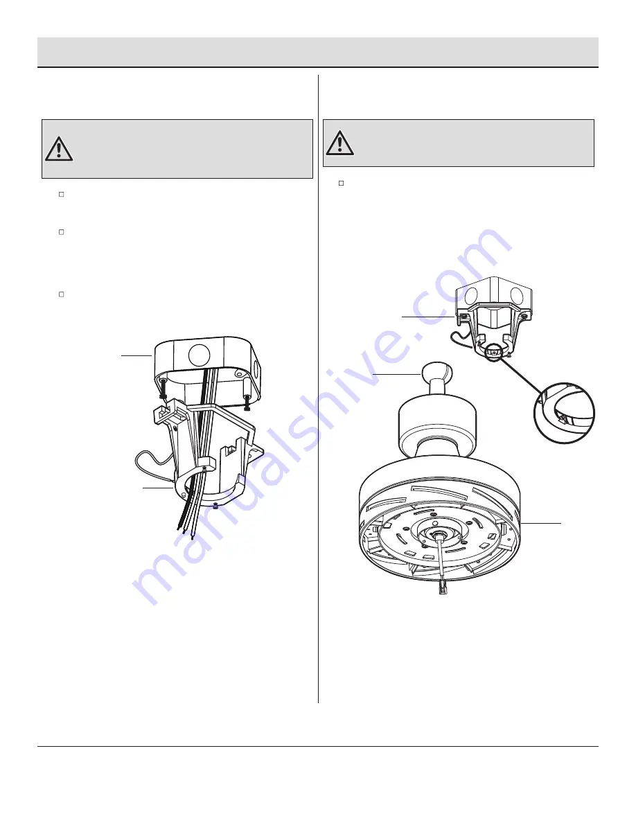
Attaching the mounting bracket to the
electrical box

Hanging the fan on the mounting
bracket

5

Pass the 120-volt supply wires through the center hole in 
the mounting bracket (A).

Attach the mounting bracket (A) on the outlet box by sliding 
the mounting bracket (A) over the screws provided with the 
outlet box. Note that the flat side of the mounting bracket 
(A) is toward the outlet box.

Securely tighten the two mounting screws.

Carefully lift the fan motor assembly (F) up to the mounting 
bracket (A) and seat the hanger ball/downrod assembly (D) 
in the mounting bracket (A) socket. Make sure the tab on the 
mounting bracket (A) socket is properly seated in the groove 
in the hanger ball/downrod assembly (D). This will help to 
balance the ceiling fan.

WARNING:


To reduce the risk of fire, electric shock or other 

personal injury, mount the fan only to an outlet box or supporting 
system marked acceptable for fan support and use the mounting 
screws provided with the outlet box.

WARNING:


The tab in the ring must rest in the groove of

the hanger ball/downrod assembly (D). Failure to properly 
seat the tab in the groove could cause damage to the wiring.

A

D

F

A

Outlet box

Summary of Contents for AK401A-BN

Page 1: ...ng to the store 8 a m 7 p m EST Monday Friday 9 a m 6 p m EST Saturday call Hampton Bay Customer Service We appreciate the trust and confidence you have placed in Hampton Bay through the purchase of t...

Page 2: ...trical connections spliced conductors should be turned upward and pushed carefully up into the outlet box The wires should be spread apart with the grounded conductor and the equipment grounding condu...

Page 3: ...esponsibility Damage to any part such as by accident misuse improper installation or by affixing any accessories is not covered by this warranty Because of varying climatic conditions this warranty do...

Page 4: ...n to actual size HARDWARE INCLUDED Pre Installation continued DD AA BB CC AA BB CC DD Plastic wire nut Blade attachment screw and lock washer additional 1 5V AAA battery 3 pin extension cord Part Desc...

Page 5: ...ng bracket preassembled Canopy Canopy bottom cover preassembled Hanger ball downrod assembly Coupling cover Fan motor assembly PACKAGE CONTENTS Pre Installation continued HAMPTONBAY COM Please contact...

Page 6: ...ion hanger bar not included as shown above Outlet Box Outlet Box Hanger Bar Outlet Box Recessed Outlet Box A WARNING To reduce the risk of fire electric shock or personal injury mount the fan to an ou...

Page 7: ...r ball lower the hanger ball and remove the pin Remove all three pieces from the downrod and assemble them onto the new longer downrod before proceeding to the downrod installation Be sure to snap tog...

Page 8: ...F up to the mounting bracket A and seat the hanger ball downrod assembly D in the mounting bracket A socket Make sure the tab on the mounting bracket A socket is properly seated in the groove in the...

Page 9: ...e remote control and the fan s receiving unit NOTE If a longer downrod not included is needed use the extension cord DD to connect with the motor wires and receiver CAUTION Do not use with a wall ligh...

Page 10: ...the loose canopy mounting screws EE on the mounting bracket A Turn the canopy B clockwise until it locks in place at the narrow section of the key holes Make sure the positioning pin JJ on the mounti...

Page 11: ...light kit mounting plate While holding the 20W LED light kit I under the fan motor assembly F snap together the wire connection plugs LL White to white Black to black Position the notches MM in the ou...

Page 12: ...ill start to spin The fan will now accept commands from the added remote If you would like to set the dip switch back to the 0 position after a learning please re pair the remote by following the lear...

Page 13: ...lated Color Temperature CCT changing Push and release the button to cycle through the three color temperature options Option 1 3000K Soft White Option 2 4000K Bright White Option 3 5000K Daylight Fan...

Page 14: ...he remote control holder SS orient the remote control holder SS by lining up the two mounting holes with those on the remote control bracket PP Insert and tighten the screws TT Operation continued INS...

Page 15: ...lide the switch to the left for warm weather operation Slide the switch to the right for cool weather operation Warm weather Counterclockwise Direction A downward air flow creates a cooling effect Thi...

Page 16: ...ble occurs after running the fan for 10 minutes verify blade level using the following process Select a point on the ceiling above the tip of one of the blades then select any fan blade and measure fr...

Page 17: ...pursuant to Part 15 of the FCC Rules These limits are designed to provide reasonable protection against harmful interference in a residential installation This equipment generates uses and can radiate...

Reviews: