background image

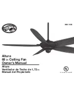
Altura

68 

in

 Ceiling Fan

Owner’s Manual

Altura

Ventilador de Techo de 1,72 

m

Manual del Propietario

xxx xxx

UL model no: 68-ATR

150 mm

213 mm

The spot color is for reference  proof only, please follow 

pantone guide for actual color when printing.

This line is for die-cut position only

DO NOT PRINT IT!!!

Black

Magenta

Yellow

Black

PMS 465C PMS 5425C PMS 632C

Die

Total Colors

1C

Coating

Varnish

ADDITIONAL INFORMATION

V0.0

09-12-31

V0.0

17 Apr 09

V0.0

17 Apr 09

V0.0

17 Apr 09

V0.0

17 Apr 09

V0.0

17 Apr 09

V0.0

17 Apr 09

V0.0

17 Apr 09

V0.0

17 Apr 09

V0.0

17 Apr 09

V0.0

17 Apr 09

V0.0

17 Apr 09

V0.0

17 Apr 09

V0.0

17 Apr 09

V0.0

17 Apr 09

1. UPC at 100% and without truncated.

2. The smallest fonts size is 6 points in the artwork.

File Name:

Artwork Version:

Customer:

Buyer:

Sold In Country:

Item Number:

Catergory:

MVendor:

Printing Type:

Translation Agency:

Size:

Blank Size:

Artist:

C.S.:

Date:

HD_014853A_904384_MC

V0.0

Home Depot

N/A

US

TBA

Ceiling Fan

KOF

Offest

TBA

213(L) x 150(W) mm

213(L) x 150(W) mm

James

Janice

09-12-31

Summary of Contents for Altura

Page 1: ...nce proof only please fo pantone guide for actual color when printing This line is for die cut position only DO NOT PRINT IT V0 0 17 Apr 09 V0 0 17 Apr 09 V0 0 17 Apr 09 V0 0 17 Apr 09 V0 0 17 Apr 09 V0 0 17 Apr 09 V0 0 17 Apr 09 V0 0 17 Apr 09 V0 0 17 Apr 09 V0 0 17 Apr 09 V0 0 17 Apr 09 V0 0 17 Apr 09 V0 0 17 Apr 09 V 17 A Artist C S Date James Janice 09 12 31 ...

Page 2: ... Please reference your SKU xxx xxx oil rubbed bronze or UPC 082392 610685 oil rubbed bronze Thank you for purchasing this Hampton Bay ceiling fan This product has been manufactured with the highest standards of safety and quality The finish of this fan is weather resistant but over time will naturally weather and fade Safety Rules 1 Unpacking Your Fan 2 Installing Your Fan 3 Operating Your Fan 9 O...

Page 3: ...st cleaning After making electrical connections spliced conductors 10 should be turned upward and pushed carefully up into outlet box The wires should be spread apart with the grounded conductor and the equipment grounding conductor on one side of the outlet box Electrical diagrams are for reference only Light kits that are 11 not packed with the fan must be UL Listed and marked suit able for use ...

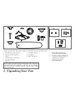
Page 4: ...r 9 Mounting Plate inside canopy 1 Downrod and Ball Assembly 2 Canopy 3 Decorative Motor Collar Cover 4 Fan Motor Assembly 5 Blades 5 6 2 Unpacking Your Fan IMPORTANT THISPRODUCTAND ORCOMPONENTSARECOVEREDBY ONEORMOREOFTHEFOLLOWINGU S PATENTS 5 947 436 5 988 580 5 971 573 6 010 110 6 010 306 6 039 541 6 046 416 AND OTHER PATENTS PENDING Unpack your fan and check the contents You should have the fol...

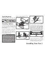
Page 5: ...ain proper blade clearance when install ing on a steep sloped ceiling The maximum angle allowable is 30 If the canopy touches downrod remove the decorative canopy bottom cover and turn the canopy 180 before attaching the canopy to the mounting plate Outlet Box To hang your fan where there is an existing fixture but no ceiling joist you may need an installation hanger bar as shown in Figure 4 avail...

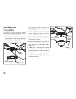
Page 6: ...r cover then the canopy ring Make sure the slot openings are on top Route the wires through the canopy and then through the ball downrod assembly Figure 7 Loosen but do not remove the set 4 screws on the collar on the top of the motor housing Align the holes at the bottom of the 5 downrod with the holes in the collar on top of the motor housing Figure 7 Carefully insert the hanger pin through the ...

Page 7: ...n Follow the steps below to connect the fan to your household wiring Use the wire connecting nuts supplied with your fan and supplied with remote control Se cure the connectors with electrical tape Make sure there are no loose strands or connections Figure 9 Connect both green wires from the down 1 rod and mounting plate to the bare copper Ground from the outlet box Connect the black wire AC IN L ...

Page 8: ...IRING CONSULT AND ELECTRICIAN FOR THE PROPER SIZE WIRE NUTS TO USE THE FREQUENCIES ON YOUR RECEIVER AND TRANSMITTER HAVE BEEN PRESET AT THE FACTORY BEFORE INSTALLING THE RECEIV ER MAKE SURE THE DIP SWITCHES ON THE RECEIVER AND TRANSMITTER ARE SET TO THE SAME FREQUENCY THE DIP SWITCHES ON THE TRANSMITTER ARE LOCATED INSIDE THE BATTERY COMPARTMENT Finishing the Fan Installation STANDARD CEILING MOUN...

Page 9: ... after each step Check that all blade screws are secure 1 Most fan wobble problems are caused when 2 blade levels are unequal Check this level by selecting a point on the ceiling above the tip of one of the blades Measure from a point on the center of each blade to the point on the ceiling Measure this distance as shown in Figure 11 Rotate the fan until the next blade is positioned for measurement...

Page 10: ... are situated in the narrow end of the keyholes Re install the one serrated head screw that 4 was removed in step 1 Tighten all three ser rated head screws firmly Remove one serrated head screw from the 5 switch box adaptor Loosen but do not re move the other two serrated head screws Figure 13 Aligning the L shape holes on the switch 6 box with the serrated head screw on the switch box adaptor Tur...

Page 11: ...lide the reversing switch located at the top of the motor housing refer to figure 7 on page 5 to opposite position and turn fan on again The fan blades will turn in the opposite direction and reverse the airflow Speed 1 The remote features Low Med Hi and Off buttons to select the desired speed of operation and turn the fan On or Off Lights 2 To control the light kit the remote features a light Dim...

Page 12: ... code combinations To prevent possible interference from or to other remote units such as garage door openers car alarm or security system simply change the combination code but be sure that the code on both the hand held trans mitter and receiver in the fan are matched Install a 9 volt battery not included Operating the Fan Hi Key High Speed Med Key Medium Speed Low Key Low Speed Off Key Power Of...

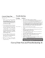
Page 13: ...SECTION MAKING ELECTRICAL CONNECTIONS Fan will not start Fan sounds noisy Check main and branch circuit fuses or breakers 1 Check line wire connections to the fan and switch wire connections in 2 the switch housing CAUTION Make sure main power is off Check batteries in the transmitter Does the red LED light come on Are 3 you standing close enough to the fan Normal range is 10 20 feet Are the dip s...

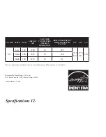
Page 14: ...IGHER IS BETTER CFM WATT N W G W C F 68 Low 120 3780 16 225 33 9 Lbs 37 8 Lbs 3 34 Med 120 5453 36 148 High 120 8752 95 91 These are approximate measures They do not include Amps and Wattage used by the light kit Distributed by Home Depot U S A Inc 2455 Paces Ferry Rd N W Atlanta Georgia 30339 Vendor Number 11688 ...

Page 15: ...is normal and should not be considered a defect Servicing performed by un authorized persons shall render the warranty invalid There is no other express warranty Hampton Bay hereby disclaims any and all warranties including but not limited to those of merchantability and fitness for a particular purpose to the extent permitted by law The duration of any implied war ranty which cannot be disclaimed...

Reviews: