background image


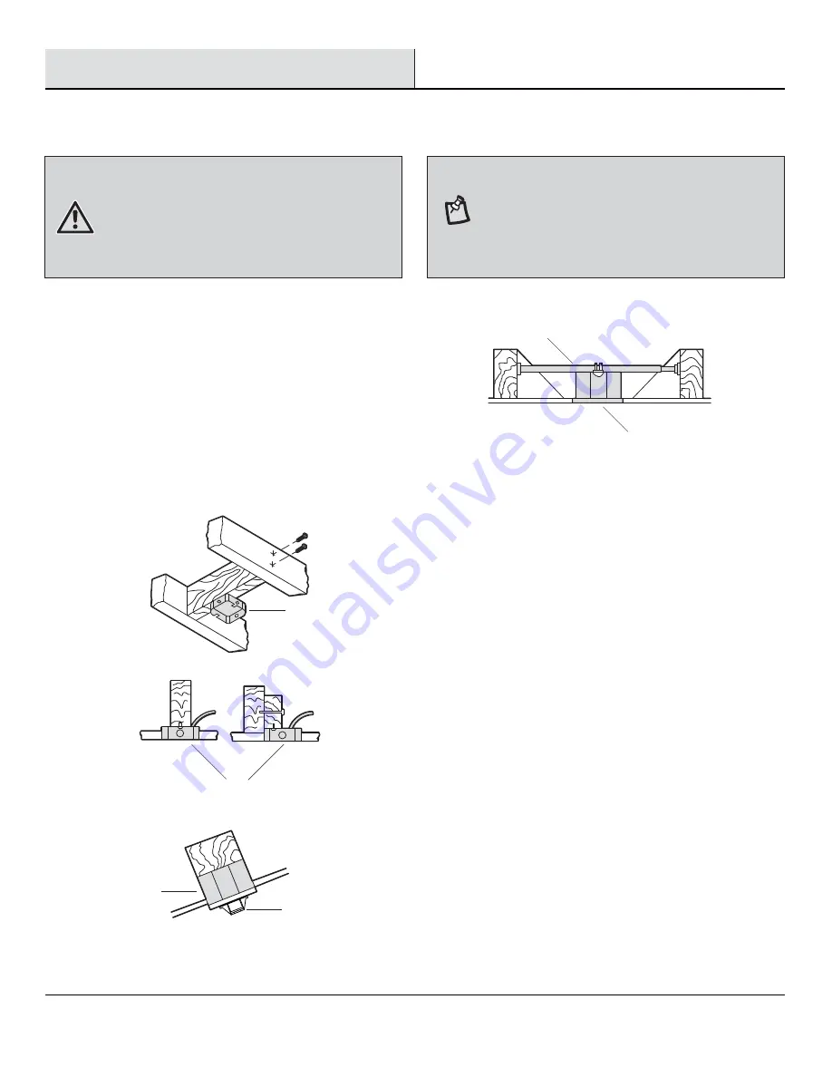
To hang your fan where there is an existing fixture but no ceiling 
joist, you may need an installation hanger bar (MM) (not 
included) as shown above.

If your ceiling fan does not have an existing UL-listed mounting 
box, then install one using the following instructions:


Disconnect the power by removing the fuses or turning off 
the circuit breakers.


Secure the outlet box (LL) (not included) directly to the 
building structure. Use appropriate fasteners and materials 
(not included). The outlet box and its bracing must be able 
to fully support the weight of the moving fan (at least 35 
lbs.). Do not use a plastic outlet box.

The illustrations below show three different ways to mount the 
outlet box (LL) (not included).

LL

LL

MM

LL

LL

A

Installation 

MOUNTING OPTIONS

MOUNTING OPTIONS


WARNING:


To reduce the risk of fire, electric shock, or 

personal injury, mount the fan to an outlet box marked 
acceptable for fan support using the screws provided with the 
outlet box. An outlet box commonly used for the support of 
lighting fixtures may not be acceptable for fan support and 
may need to be replaced. If in doubt, consult a qualified 
electrician.

8

NOTE:


You may need a longer downrod to maintain proper 

blade clearance when installing on a steep, sloped ceiling. 
The maximum angle allowable is 18° away from horizontal. If 
the canopy (C) touches the hanger ball/downrod assembly (E), 
then remove the decorative canopy bottom cover (D) and turn 
the canopy (C) 180° before attaching the canopy (C) to the 
mounting bracket (A).

Summary of Contents for ASHBURTON YG593-WH

Page 1: ...G FAN THANK YOU THANK YOU Item 0000000000 Model YG593 WH 1 855 HD HAMPTON HAMPTONBAY COM Questions problems missing parts Before returning to the store 8 a m 7 p m EST Monday Friday 9 a m 6 p m EST Sa...

Page 2: ...ting Instructions Installation Assembly Standard Ceiling Mounting Close to Ceiling Mounting Hanging the Fan Attaching the Fan Blades 2 3 4 4 4 4 5 6 7 8 9 9 10 11 14 16 Operation Pull Chain Operating...

Page 3: ...After making electrical connections spliced conductors should be turned upward and pushed carefully up into the outlet box The wires should be spread apart with the grounded conductor and the equipmen...

Page 4: ...gest useful life when protected from varying weather conditions A certain amount of wobble is normal and should not be considered a defect Servicing performed by unauthorized persons shall render the...

Page 5: ...with lock washer preassembled Blade arm screw with lock washer preassembled Light kit mounting plate screw preassembled Switch housing mounting screw preassembled Pull chain and fob not to scale Plast...

Page 6: ...tity Quantity 1 5 5 1 1 Part Part A B C D E F Quantity Quantity 1 1 1 1 1 1 Description Description Mounting bracket preassembled Canopy ring preassembled Canopy Canopy bottom cover preassembled Hange...

Page 7: ...standard downrod installation the distance from the ceiling to the bottom of the fan blades will be approximately 12 in The close to ceiling installation reduces the distance from the ceiling to the...

Page 8: ...ree different ways to mount the outlet box LL not included LL LL MM LL LL A Installation MOUNTING OPTIONS MOUNTING OPTIONS WARNING To reduce the risk of fire electric shock or personal injury mount th...

Page 9: ...then through the hanger ball downrod assembly E Align the holes at the bottom of the hanger ball downrod assembly E with the holes in the collar on top of the fan motor assembly G Carefully insert the...

Page 10: ...ing B and canopy C over the collar at the top of the fan motor assembly G Align the mounting holes in the bottom of the canopy C with the holes in the top of the fan motor assem bly G Fasten using the...

Page 11: ...shock or other personal injury mount the fan only to an outlet box or supporting system marked acceptable for fan support and use the mounting screws provided with the outlet box WARNING The tab in t...

Page 12: ...o your household wiring Use the plastic wire nuts AA with your fan Secure the plastic wire nuts AA with electrical tape Make sure there are no loose strands or connections Connect the ground conductor...

Page 13: ...w with lock washer BB included with your fan Slide the canopy ring B over the canopy C and tighten by turning the ring B Remove the fan from the hook on the mounting bracket A Secure the canopy C to t...

Page 14: ...blade H engages in the spring locking mechanism QQ Make sure the spring of the spring locking mechanism QQ is upward and the butt of the spring locking mechanism QQ is against the edge of the blade N...

Page 15: ...n Do not insert foreign objects between rotating fan blades H Fasten the blade assemblies to the fan motor assembly G by lining up the slots RR of the motor with the tabs on the blade arms SS Tighten...

Page 16: ...plate screws HH previously loosened and the one HH previously removed HH J TT CAUTION Before starting installation disconnect the power by turning off the circuit breaker or removing the fuse at the...

Page 17: ...blade rotation REVERSE SWITCH OPERATING INSTRUCTIONS REVERSE SWITCH OPERATING INSTRUCTIONS The reverse switch is located on the surface of the switch housing Slide the switch to the left for warm wea...

Page 18: ...power is off at the electrical panel box before you attempt any repairs Refer to step 6 Making the Electrical Connections on page 12 Problem Problem Solution Solution Check the main and branch circui...

Page 19: ...hen select any fan blade and measure from the center of the selected blade to the point on the ceiling Rotate the fan until the next blade is positioned and repeat the measurement using the same point...

Page 20: ...rt Part AA BB CC DD EE FF GG HH II JJ KK Description Description Plastic wire nut Canopy mounting screw with lock washer preassembled Clevis pin preassembled Cotter pin preassembled Collar setscrew pr...

Page 21: ...N HAMPTONBAY COM Retain this manual for future use YG593WH001 A Questions problems missing parts Before returning to the store 8 a m 7 p m EST Monday Friday 9 a m 6 p m EST Saturday call Hampton Bay C...

Reviews: