background image

12

XX

XX

Operating Your Fan

Turn on the power and check the operation of the fan. 
The pull chain controls the fan speeds as follows: 
1 pull - High
2 pulls - Medium
3 pulls - Low
4 pulls - off 
The appropriate speed settings for warm or cool weather depends on 
factors such as the room size, ceiling height, and number of fans. 
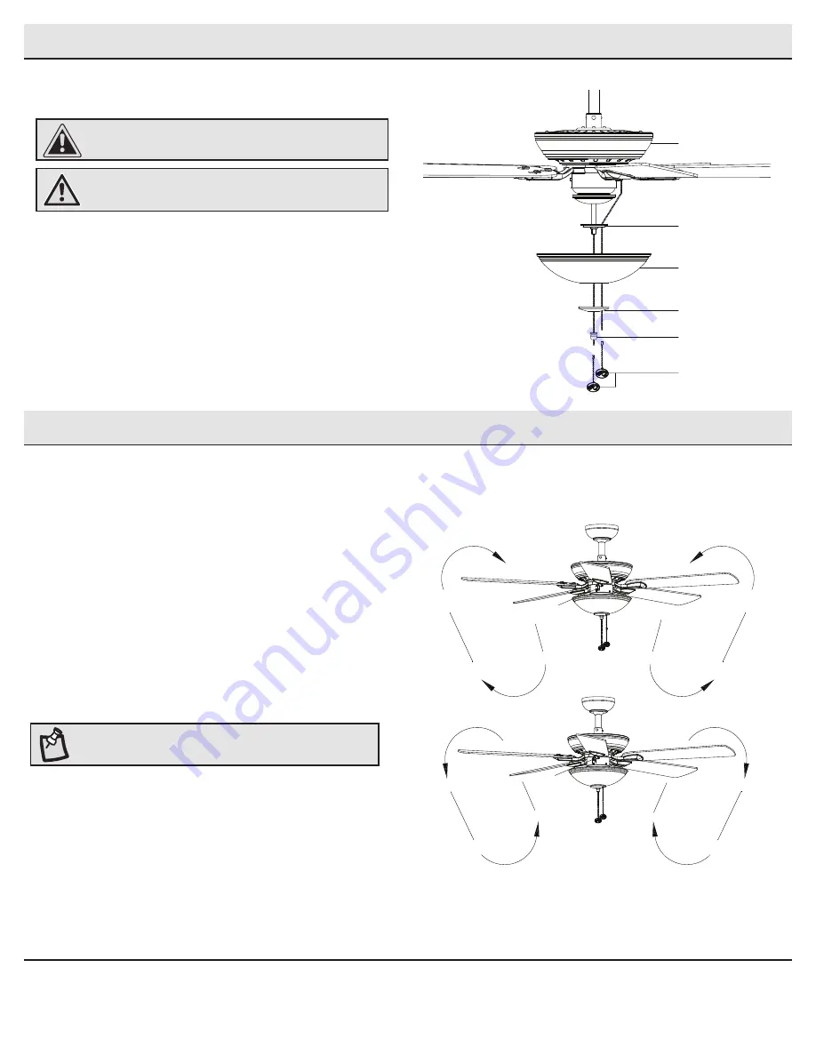
The fan is shipped from the factory with the reversing switch 
positioned to circulate air downward. If airflow is desired in the 
opposite direction, turn your fan off and wait for the blades to stop 
turning, then slide the reversing switch (XX) (located in switch cup) to 
the opposite position, and turn the fan on again. The fan blades will 
turn in the opposite direction and reverse airflow. 

Warm weather

 - Warm weather - (Forward) A downward airflow creates 

a cooling effect. This allows you to set your air conditioner on a warmer 
setting without affecting your comfort.

Cool weather

 - (Reverse) An upward airflow moves warm air off of the

ceiling. This allows you to set your heating unit on a lower setting
without affecting your comfort.

A. Warm weather

B. Cool weather

Installing the shatter resistant bowl

2        


Position the shatter resistant bowl shade (G) over the 
threaded nipple and pass the pull chain for the fan through 
the pull chain guide (VV) on the side of the light kit (F) to 
avoid the chain from touching the shatter resistant bowl 
shade (G).


Install shade holder (LL), and finial (KK) to the threaded 
nipple to secure the shatter resistant bowl shade (G) 
properly.


Attach the pull chain extensions (AA). 

CAUTION:

  Make sure the power is off before attaching or 

removing the shatter resistant bowl.

WARNING:

 Allow the shatter resistant bowl to cool completely 

before removing.

Assembly - Attaching the Light Kit (continued)

NOTE:

 Wait for the fan to stop before reversing the direction of 

the blade rotation.

AA

KK

LL

VV

E

G

Summary of Contents for COMFORT BREEZE 68131

Page 1: ...the outlet box 13 Do not mix old and new batteries 14 Do not mix alkaline standard carbon zinc or rechargeable ni cad ni mh etc batteries NOTE The ceiling fan must be set at HIGH speed and light kit i...

Page 2: ...pton Bay through the purchase of this ceiling fan We strive to continually create quality products designed to enhance your home Visit us online to see our full line of products available for your hom...

Page 3: ...you are installing Switches must be UL General Use Switches Refer to the instructions packaged with the light kits and switches for proper assembly 9 After making electrical connections spliced condu...

Page 4: ...sories is not covered by this warranty Because of varying climatic conditions this warranty does not cover any changes in brass finish including rusting pitting corroding tarnishing or peeling Brass f...

Page 5: ...Part Description Quantity AA Pull chain 2 BB Plastic wire connector 3 CC Hanging pin 1 DD Locking pin 1 Pre Installation continued HARDWARE INCLUDED NOTE Hardware not shown to actual size AA CC BB DD...

Page 6: ...ownrod assembly 1 E Fan motor assembly 1 F Light kit fitter assembly 1 G Shatter resistant shade 1 Part Description Quantity H Blade 5 I Blade arm 5 IMPORTANT This product and or components are govern...

Page 7: ...se the appropriate fasteners and materials The outlet box and its bracing must be able to fully support the weight of the moving fan at least 35 lbs Do not use a plastic outlet box The illustrations b...

Page 8: ...the mounting bracket A and turn the canopy counterclockwise to remove the mounting bracket A from the canopy B Assembling the fan Loosen but do not remove the 2 setscrews ZZ on the collar on top of t...

Page 9: ...e outlet box Securely tighten the two mounting screws JJ Carefully lift the fan motor assembly E up to the slide on mounting bracket A Seat the hanger ball portion of the ball downrod assembly D in th...

Page 10: ...larger than 12 gauge house wiring or more than one house wire to connect to the fan wiring consult an electrician for the proper size wire nuts to use Please refer to remote installation instructions...

Page 11: ...screws FF and alignment post EE in the mounting bracket A Push up the canopy B and turn clockwise until the alignment post EE engages to the round hole and the screws FF engage to the key slots Firml...

Page 12: ...he top of the blade brackets I Hold the blade H close to the blade bracket I and press the blade H down firmly Ensure the key slot holes are properly seated on the blade arm posts While still holding...

Page 13: ...ur air conditioner on a warmer setting without affecting your comfort Cool weather Reverse An upward airflow moves warm air off of the ceiling This allows you to set your heating unit on a lower setti...

Page 14: ...n wobbles Check that all blade and blade arm screws are secure Most fan wobble problems are caused when blade levels are unequal Check this level by selecting a point on the ceiling above the tip of o...

Page 15: ...or more of the following measures Reorient or relocate the receiving antenna Increase the separation between the equipment and receiver Connect the equipment into an outlet on a circuit different fro...

Reviews: