background image

8

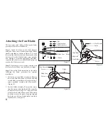
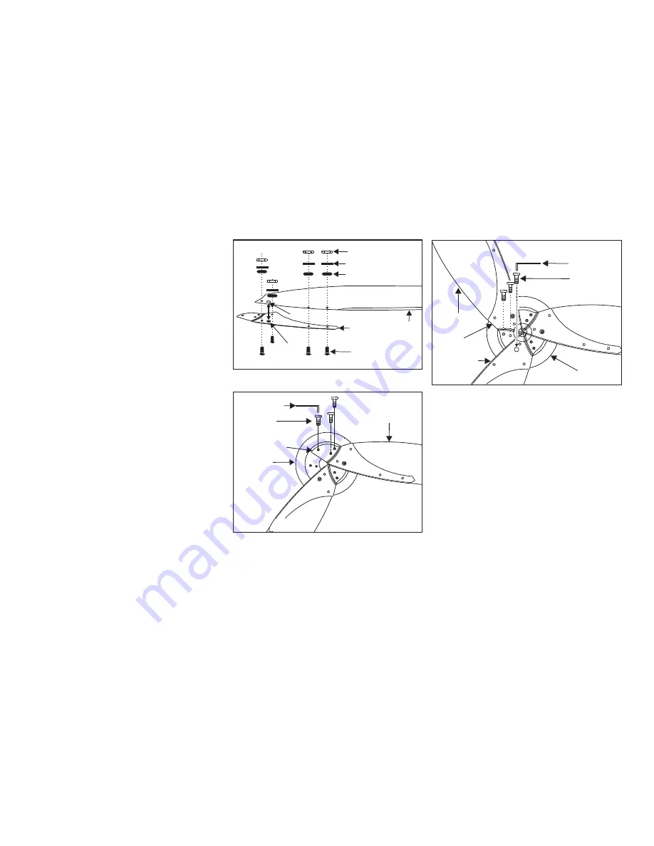
Attaching the Fan Blades

For first and second blade assemblies: Remove 
the screws from the motor, attach the first and 
second blade assemblies to the motor using 3 
screws provided, secured with Allen wrench. 
(Figure 14)

For third blade assembly: Remove the screws 
from the motor, attach the third blade assembly 
to the motor by securing 2 of 3 screws provided 
at first, secured with Allen wrench. Then attach 
the third screw to the motor by going through 
the holes on the first blade bracket and third 
blade bracket, see Figure 15.
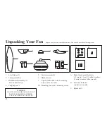
1.

2.

This fan comes with 3 blades, following the below 
procedure for accurate installation:
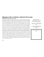
Step 1.

 Attach the blades to the blade brackets 

using the screws, nuts, metal washers and rubber 
washers provided as shown in Figure 13, be sure 
the jut on the blade bracket to be positioned on the 
hole located on the blades before screw installa-
tion. Starting a screw into the bracket and blade, 
repeat for the other 3 screws, 

DO NOT

 tighten too 

much as the blades may crack.

Step 2.

 Tighten each screw securely starting with 

the center screw. Make sure the blade is straight.

Step 3.

 Fasten the blade assemblies to the motor 

following the below procedure for accurate 
installation.

Figure 13

Rubber washers

Blade Arm


Nut
Metal washers

Blade

Screws

Jut

Hole

Figure 15

Screws

Allen Wrench

Motor

First Blade

Blade Arm

Third Blade

Screws

Motor

Figure 14

Blade

Allen Wrench

Blade Arm

Summary of Contents for Florentine

Page 1: ...Florentine IV 56 in Ceiling Fan Owner s Manual Florentine IV Ventilador de Techo de 1 42 m Manual del Propietario 527 541 ...

Page 2: ...Florentine IV by Hampton Bay ...

Page 3: ...has been manufactured with the highest standards of safety and quality The finish of this fan is weather resistant but over time will naturally weather and fade Table of Contents Safety Rules 1 Unpacking Your Fan 2 Installing Your Fan 3 Operating Your Fan 9 Care of Your Fan 10 Troubleshooting 10 Specifications 11 Warranty Information 12 527 541 792145354390 219032 ...

Page 4: ...ades To avoid personal injury or damage to the fan and other items be cautious when working around or cleaning the fan Do not use water or detergents when cleaning the fan or fan blades A dry dust cloth or lightly dampened cloth will be suitable for most cleaning After making electrical connections spliced conductors should be turned upward and pushed carefully up into outlet box The wires should ...

Page 5: ... cover 1 2 3 4 Fan motor assembly Blade arms 3 4 speed wall control with 2 mounting screws and 3 wire nuts Mounting plate with 2 mounting screws 5 6 7 7A Blade Attachment Hardware 13 screws 13 nut 13 rubber washers 13 metal washers Allen wrench Electrical Hardware 3 plastic wire nuts Balance Kit A B C WARNING DO NOT INSTALL OR USE FAN IF ANY PART IS DAMAGED OR MISSING CALL TOLL FREE 1 877 902 5588...

Page 6: ... SCREWS PROVIDED WITH THE OULET BOX OUTLET BOX COMMONLY USED FOR THE SUPPORT OF LIGHTING FIXTURE MAY NOT BE ACCEPTABLE FOR FAN SUPPORT AND MAY NEED TO BE REPLACED CONSULT A QUALIFIED ELECTRICIAN IF IN DOUBT Outlet Box Outlet Box Outlet Box Figure 2 Figure 1 Note You may need a longer downrod to maintain proper blade clearance when installing on a steep sloped ceiling The maximum angle allowable is...

Page 7: ...evis pin cotter pin and set screws from the top of the motor assembly Figure 6 Route wires exiting from the top of the fan motor through the coupling cover canopy cover canopy and then through the ball downrod Figure 6 Align the holes at the bottom of the downrod with the holes in the coupling on top of the motor housing Figure 6 Carefully insert the clevis pin through the holes in the collar and ...

Page 8: ...e mounting bracket socket Make sure the tab on the mounting bracket socket is properly seated in the groove in the hanger ball Figure 8 This will help to balance the ceiling fan Changing the Downrod Optional 1 2 3 4 NOTE Your fan comes with a 4 downrod attached to the hanger ball In addition you have been provided with a 6 downrod to use if desired If you choose to use the 6 downrod perform the fo...

Page 9: ...source White wire from fan to white wire from the A C supply source Connect the fan ground wire green to the household ground wire If your outlet box has a ground wire green or bare copper connect the wall transmitter s 1 2 3 4 ground wire to it otherwise connect the wall transmitter s ground wire directly to one of the screws from the outlet box If you feel you do not have enough electrical wirin...

Page 10: ...et and place the key hole on the canopy over the screw on the mounting bracket turn canopy until it locks in place at the narrow section of the key holes Fig 12 Align the circular hole on canopy with the remaining hole on the mounting bracket secure by tightening the two set screws Note Adjust the canopy screws as necessary until the canopy and canopy cover are snug 1 2 3 Finishing the Fan Install...

Page 11: ...accurate installation Step 1 Attach the blades to the blade brackets using the screws nuts metal washers and rubber washers provided as shown in Figure 13 be sure the jut on the blade bracket to be positioned on the hole located on the blades before screw installa tion Starting a screw into the bracket and blade repeat for the other 3 screws DO NOT tighten too much as the blades may crack Step 2 T...

Page 12: ...t blade is positioned for measurement Repeat for each blade Measurements deviation should be within 1 8 Run the fan for 10 Minutes Use the enclosed Blade Balancing Kit if the blade wobble is still noticeable 1 2 3 The following procedure should correct most fan wobble Check after each step Figure 16 Touching Ceiling Restore power to ceiling fan and test for proper operation The fan 4 speed control...

Page 13: ...polish to the wood blades for additional protection and enhanced beauty Cover small scratches with a light application of shoe polish There is no need to oil your fan The motor has permanently lubricated sealed ball bearings 1 2 3 4 Here are some suggestions to help you maintain your fan Check main and branch circuit fuses or breakers Check line wire connections to the fan Make sure all motor hous...

Page 14: ...RPM CFM N W G W C F 56 120 8 63 kgs 19 04 lbs 10 0 kgs 22 06 lbs 1 36 Low Medium Medium High High 0 17 0 24 0 39 0 48 9 14 35 54 49 69 113 150 1396 1908 3608 5136 These are approximate measures They do not include Amps and Wattage used by the light kit ...

Page 15: ...unauthorized persons shall render the warranty invalid There is no other express warranty Hampton Bay hereby disclaims any and all warranties including but not limited to Those of merchantability and fitness for a particular purpose to the extent permitted by law The duration of any implied warranty which cannot be disclaimed is limited to the time period as specified in the express warranty Some ...

Reviews: