background image

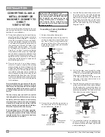
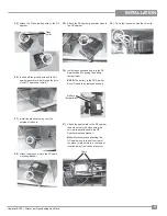
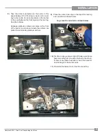
Hampton® H15-1 Direct Vent Freestanding Gas Stove

41

MAINTENANCE

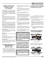
Top View of pilot fl ame

MAINTENANCE 

INSTRUCTIONS

1)

  Always turn off the valve before cleaning. For 

relighting, refer to lighting instructions. Keep 
the burner and control compartment clean by 
brushing and vacuuming at least once a year. 
When cleaning the logs, use a soft clean paint 
brush as the logs are fragile and easily dam-
aged.

Top View of pilot fl ame

Incorrect fl ame pattern will have small, probably 
yellow fl ames, not coming into proper contact 
with the rear of the burner or thermopile. 

NORMAL OPERATING 

SOUNDS OF GAS 

APPLIANCES

It is possible that you will hear some sounds from 
your gas appliance. This is perfectly normal due 
to the fact that there are various gauges and types 
of steel used within your appliance. Listed below 
are some examples. All are 

normal operating 

sounds 

and should not be considered as defects 

in your appliance.

Blower: 

Hampton

®

 gas appliances use high tech blowers 

to push heated air farther into the room. It is not 
unusual for the fan to make a "whirring" sound 
when ON. This sound will increase or decrease 
in volume depending on the speed setting of your 
fan speed control.

Burner Tray: 

The burner tray is positioned directly under the 
burner tube(s) and logs and is made of a different 
gauge material from the rest of the fi rebox  and 
body. Therefore, the varying thicknesses of steel 
will expand and contract at slightly different rates 
which can cause "ticking" and "cracking" sounds. 
You should also be aware that as there are tempera-
ture changes within the unit these sounds will likely 
re-occur. Again, this is normal for steel fi reboxes.

Blower Thermodisc: 

When this thermally activated switch turns ON it will 
create a small "clicking" sound. This is the switch 
contacts closing and is normal.

Pilot Flame:


While the pilot fl ame is on it can make a very slight 
"whisper" sound.

Gas Control Valve:


As the gas control valve turns ON and OFF, a 
dull clicking sound may be audible, this is normal 
operation of a gas regulator or valve.

Unit Body/Firebox:


Different types and thicknesses of steel will expand 
and contract at different rates resulting in some 
"cracking" and "ticking" sounds will be heard 
throughout the cycling process.

8) 

Each time the appliance is lit, it may cause 

condensation and fog the glass.  This condensa-
tion and fog is normal and will disappear in a few 
minutes as the glass heats up.


Never operate the appliance without the 
glass properly secured in place.

9) 

Periodically check the pilot fl ames.  Correct 
fl ame pattern has three strong blue fl ames: 1 
fl owing around the thermopile and 1 around the 
thermocouple, and 1 fl owing across the rear of 
the burner (it does not have to be touching the 
burner).

Note:  If you have an incorrect fl ame pattern, 

contact your Hampton

®

 dealer for further 

instructions.

2)

  Clean glass (never when unit is hot), appliance, 

and door with a damp cloth.  Never use an 
abrasive cleaner. 

3)

  The heater is fi nished in a porcelain fi nish  or 

with a heat resistant paint and should only be 
refi nished with heat resistant paint (not with 
wall paint). 


Never use an abrasive cleaner on the porcelain 
fi nish as it may scratch the surface.

4)

  Make a  periodic check of burner for proper posi-

tion and condition. Visually check the fl ame of 
the burner periodically, making sure the fl ames 
are steady; not lifting or fl oating. If there is a 
problem, call a qualifi ed service person. 

5)


Caution: Label all wires prior to disconnec-
tion when servicing controls. Wiring errors 
can cause improper and dangerous opera-
tion.

6)

  The appliance and venting system must be 

inspected before use, and at least annually, 
by a qualifi ed  fi eld service person, to ensure 
that the fl ow of combustion and ventilation air 
is not obstructed. 


During the annual service call, the burner should 
be removed from the burner tray and cleaned. 
Replace the embers but do not block the pilot.

7)

  Keep the area near the appliance clear and free 

from combustible materials, gasoline, and other 
fl ammable vapours and liquids.

PILOT ADJUSTMENT

WARNING:  CHILDREN AND ADULTS 
SHOULD BE ALERTED TO THE HAZ-
ARDS OF HIGH SURFACE TEMPERA-
TURE AND SHOULD STAY AWAY TO 
AVOID BURNS OR CLOTHING IGNI-
TION.  YOUNG CHILDREN SHOULD 
BE CAREFULLY SUPERVISED WHEN 
THEY ARE IN THE SAME ROOM AS 
THE APPLIANCE.

DO NOT USE THIS APPLIANCE IF 
ANY PART HAS BEEN UNDER WA-
TER. IMMEDIATELY CALL A QUALI-
FIED SERVICE TECHNICIAN TO 
INSPECT THE APPLIANCE AND TO 
REPLACE ANY PART OF CONTROL 
SYSTEM AND ANY GAS CONTROL 
WHICH HAS BEEN UNDER WATER

CAUTION: ANY SAFETY SCREEN OR 
GUARD REMOVED FOR SERVICING 
AN APPLIANCE MUST BE REPLACED 
PRIOR TO OPERATING THE APPLI-
ANCE.

CLOTHING OR OTHER FLAMMABLE 
MATERIAL SHOULD NOT BE PLACED 
ON OR NEAR THE APPLIANCE.

Summary of Contents for H15

Page 1: ...Y What to do if you smell gas Do not try to light any appliance Do not touch any electrical switch do not use any phone in your building Immediately call your gas supplier from a neighbour s phone Fol...

Page 2: ...fted appliance and has been designed to provide you with all the warmth and charm of a wood fireplace at the flick of a switch The model H15 1 has been approved by Warnock Hersey for both safety and e...

Page 3: ...Hampton H15 1 Direct Vent Freestanding Gas Stove 3 Hampton H15 1 Direct Vent Freestanding Gas Stove 3 SAFETY LABEL DIMENSIONS UNIT DIMENSIONS...

Page 4: ...ATION Important Message 7 Specifications 7 Manufactured Homes After First Sale 7 Before You Start 7 General Safety Information 8 Installation Checklist 8 Clearances to Combustibles 9 Locating Your Gas...

Page 5: ...CUATION PROPANE GAS STOVE Model H15 LP1 L APPAREIL FONCTIONNANT AU PROPANE CONCU POUR ETRE POELE Mod le H15 LP1 MAY BE INSTALLED IN MANUFACTURED MOBILE HOMES AFTER FIRST SALE DO NOT REMOVE THIS LABEL...

Page 6: ...directly in line with the exhaust vent terminal for the horizontally vented gas fueled heating appliance or equipment The sign shall read in print size no less than one half 1 2 inch in size GAS VENT...

Page 7: ...Electrical Code CSA C22 1 in Canada BEFORE YOU START Safe installation and operation of this appliance re quires common sense however we are required by theCanadianSafetyStandardsandANSIStandards to...

Page 8: ...ts and circulating air passageways of the appliance be kept clean and free from excessive lint from carpeting 4 See general construction and assembly in structions The appliance and vent should be enc...

Page 9: ...OMBUSTIBLES The clearances listed are MINIMUM distances Measure the clearance to both the appliance and the chimney connector The farthest distance is correct if the two clearances do not coincide For...

Page 10: ...f 2 bolts at the top Take care not to cut wires when lower ing the panel 2 Disconnect the red and grey wires Top Control Panel Assembly Fan Speed Controller 4 Remove the nylon hole plug from the contr...

Page 11: ...properly grounded three prong receptacle Do not cut or remove the grounding prong from this plug 12 Slide fan into place and secure with the two screws removed in step 9 13 Connect long black red wir...

Page 12: ...s of combustion to the outside while the outer pipe draws outside combustion air into the combustion chambertherebyeliminatingtheneedtouseheated room air for combustion and losing warm room air up the...

Page 13: ...center line extended above meter regulator assembly 36 90cm a J Clearance to service regulator vent outlet 36 90cm K Clearance to non mechanical air supply inlet to building or the combustion air inl...

Page 14: ...N A N A Adjustable Length 3 10 Galvanized N A N A N A 4DAL N A TC 4DLT Adjustable Length 3 10 Black N A N A N A 4DALB N A TC 4DLTB Adjustable Length 7 Galvanized N A N A 4D7A N A N A N A Adjustable Le...

Page 15: ...ntal Termination Kit A Disc 4DT HKA 4DHTK2 4DHTKA SV SHK N A Horizontal Termination Kit B 46DVA KHA Changed Components 4DT HKB 4DHTK1 4DHTKB SV HK N A Vertical Termination Kit Disc 4DT VKC 4DHTK 4DHTK...

Page 16: ...nt SelkirkDirect Temp Ameri Vent Direct venting and Security Secure Vent systems Use of these systems with the Rigid Pipe adaptor is deemed acceptable and does not affect the Intertek WHI listing of c...

Page 17: ...with min of 8 feet total vertical and max 8 feet total horizontal Please note min 1 foot between 90o elbows is required With these options maxi mum total pipe length is 30 feet with minimum of 6 feet...

Page 18: ...al Please note min 1 foot between 90o elbows is re quired A 2 Max 2 Min B 3 Max 3 Min C 4 Max 4 Min D 5 Max 5 Min E 6 Max 6 Min Withtheseoptions max total pipelengthis30feetwithmin of6feettotalvertica...

Page 19: ...bustibles May be installed in Manufactured Mobile Homes after first sale Horizontal Terminations for All Venting Systems The shaded areas in the diagram below show all allowable combinations of vertic...

Page 20: ...aximum flue lengths See chart below for minimumdistancesfromroof Periodicallycheck that the vent is unrestricted Masonry chimneys may take various contours which the flexible liner will accommodate Ho...

Page 21: ...e to length Attachthe 45o elbowtotherigid pipe and ensure that the pipe length when cut with the 45o elbow will seat onto both the starter collar and the 90o elbow Crimpedsectionofrigidpipe seats into...

Page 22: ...andoff to prevent water from entering and to make a tight seal between the cap and the standoff 7 Stretch the 4 dia flex liner out fully and get a trial fit of the liner onto the 4 dia starter collar...

Page 23: ...Vent 1 946 202 Wall Penetration Heat Shield Wall Thimble 2 pcs 1 640 530 P Riser Vent Terminal 1 640 545 P Decorative Wall Trim Black 1 948 128 Tube Mill Pac Screws 380 946 Horizontal Termination Kit...

Page 24: ...ible surfaces is 1 1 4 inch Be sure to check the vent termination clearance requirements fromdecks windows soffits gasregulators air supply inlets and public walkways as specified inthe ExteriorVentTe...

Page 25: ...run of vent should have a 1 4 inch rise for every 1 foot of run towards the termination Never allow the vent to run downward Thiscouldcausehightemperatures and may present the possibility of a fire b...

Page 26: ...ighly recommended to apply Mill Pac sealant supplied to every inner pipe connection Failure to do so may result in drafting or performance issues notcoveredunderwarranty Silicone red RTV is optional D...

Page 27: ...onnection Failure to do so may result in drafting or performance issues not covered under warranty Silicone red RTV is optional and elbows necessary to reach from the appliance adapter up though the R...

Page 28: ...cured in place and sealed before installing a Direct Vent system within the chimney If the appliance shuts off during operation contact a qualified service person to determine if a negative pressure a...

Page 29: ...nd frame a hole in the roof for the support The sides of this hole must be vertical with 1 1 4 clearance 2 Place the support in the opening Lower it to the correct height as determined by the table an...

Page 30: ...finished reading manometer turn off the gas valve disconnect the hose and tighten the screw clockwise with a 1 8 flat screwdriver Note Screwshouldbesnug butdonotover tighten Valve Description 1 Gas on...

Page 31: ...0 in 904 781 Velcro Hook Black 904 782 Velcro Hook Black 1 Shut off the gas supply 2 Lift off Cast Top remove Cast Front and Glass Door refer to the glass replace ment section in the manual and carefu...

Page 32: ...ontrol panel Before After 12 Pull off the pilot cap to expose the pilot orifice 13 Unscrew the pilot orifice with the allen key and replace with the LP pilot orifice in the kit 14 Remove burner orific...

Page 33: ...iezo ignition wire to the DC Sparker Piezo Ignitor 31 Attach the heat shield to the DC sparker then mount onto the stove using the velcro already attached to the DC Sparker mounting bracket Note We re...

Page 34: ...t Side Front Log d Center Front Log e Embers f Platinum Embers 946 669 supplied with packaged manual Left Front Log 3 Remove Cast Front by removing the 2 screws using a 7 16 wrench Pull front out and...

Page 35: ...re is any flame hesitation check that area for any blockage of the burner ports 11 Re install the Glass Front Cast Front and Top 8 Take the embers and place on the burner in the space between the 2 fr...

Page 36: ...L approved may be used Thermostat Wire Table 1 Choose a convenient location on the wall to install the receiver and the receptacle box protectionfromextremeheatisveryimportant Run wires from the firep...

Page 37: ...ase of a power failure the burner switch and the optional remote control thermostat will continue to operate However a 120V A C power supply is needed for the fan blower operation Caution Ensure that...

Page 38: ...ton H15 1 Direct Vent Freestanding Gas Stove INSTALLATION For PROPANE Units and Units Equipped with DC Spark Boxes For installation of the DC Spark Box refer to the LP Conversion instructions in this...

Page 39: ...ss should be cleaned or the film will bake on and become very difficult to remove Use a non abrasive cleaner and NEVER clean the glass while it is hot I M PORTANT Gas on off knob cannot be turned from...

Page 40: ...floor WHAT TO DO IF YOU SMELL GAS Do not try to light any appliance Do not touch any electric switch do not use any phone in your building Immediately call your gas supplier from a neighbors phone Fo...

Page 41: ...timetheapplianceislit itmaycause condensation and fog the glass This condensa tion and fog is normal and will disappear in a few minutes as the glass heats up Never operate the appliance without the g...

Page 42: ...ssuch as Wall Straps or plumbers tape for rigidity LOG REPLACEMENT Theunitshouldneverbeusedwithbrokenlogs Turn off the gas valve and allow the unit to cool before opening door to carefully remove the...

Page 43: ...lace the burner tray assembly simply reverse these instructions Toremovevalvefromvalveassembly continue 14 Remove two 2 thermopile wires 15 Remove thermocouple with a 9 mm metric wrench 16 Remove pilo...

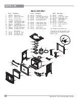
Page 44: ...Deflector Left 17 910 142 Thermodisc Switch 20 380 012 Rear Panel 25 910 330 Fan Speed Control 120V 26 904 569 Knob Fan Speed Control 28 910 241 Burner ON OFF Switch 29 260 037 Rear Control Panel 35 3...

Page 45: ...t 64 908 672 Control Panel Decal 65 490 061 Switch Plate 936 170 Orifice Gasket 66 910 038 Pilot Assy S I T 3 flame NG 910 039 Pilot Assy S I T 3 flame LP 67 380 013 Pilot Holder 68 W840470 Pilot Asse...

Page 46: ...46 Hampton H15 1 Direct Vent Freestanding Gas Stove NOTES...

Page 47: ...requested It is the general practice of FPI to charge for larger higher priced replacement parts and issue credit once the replaced component has been returned to FPI and evaluated for manufacturer d...

Page 48: ...___________________________________________________ Phone ___________________________________________________________ Date Installed ______________________________________________________ Serial No __...

Reviews: