background image


Hampton

®

 H35E-11 Direct Vent Freestanding Gas Stove

  |    

49

operating instructions

Copy of the Lighting Plate Instructions 

Part #: 919-088 - Side A

Colours: Black on white,  except for parts indicated as being Red.

       Punch out .25" hole top right corner where indicated.

Size:              100%

                         w- 6.1" x L- 9.3"


Mar 14/19:      Created decal - New Material (double sized)

Material: 

Printable white polyester 7mm

Start serial sequence @ 000001

NOTE: This is a double sided decal


Part #: 919-088 - Side B

Colours: Black on white,  except for parts indicated as being Red.

       Punch out .25" hole top right corner where indicated.

Size:              100%

                         w- 6.52"

                         h- 11.13"


Aug. 14/17:     Created decal

A)    

This appliance is equipped with an ignition device which automatically lights the pilot. 

     Do not try to light the pilot by hand.

B)  BEFORE OPERATING

 smell all around the appliance area for gas. Be sure to smell next to the floor 

     because some gas is heavier than air and will settle on the floor.


WHAT TO DO IF YOU SMELL GAS

-  Do not try to light any appliance.

-  Do not touch any electric switch, do not use any phone in your building.

-  Immediately call your gas supplier from a neighbours phone. Follow the gas supplier’s instructions.

-  If you cannot reach your gas supplier, call the fire department.

C)   

Do not use this appliance if any part has been under water.  Immediately call a qualified service 

      technician to inspect the appliance and replace any part of the control system and any 

       gas control which has been underwater.

A)  

Cet appareil est muni d’un dispositif d’allumage qui allume automatiquement la veilleuse. 

       Ne tentez pas d’allumer la veilleuse manuellement. 

B)   AVANT LA MISE EN MARCHE

, reniflez tout autour de l’appareil pour déceler une odeur de gaz. Reniflez au niveau du plancher, car certains gaz 

sont plus lourds que l’air et peuvent s’accumuler au niveau du sol.


QUE FAIRE SI VOUS SENTEZ UNE ODEUR DE GAZ :

    • Ne tentez pas d’allumer l’appareil

    • Ne touchez à aucun interrupteur; n'utilisez pas de téléphones se trouvant dans le bâtiment.

    • Appelez immédiatement votre fournisseur de gaz depuis un téléphone extérieur. Suivez les instructions du fournisseur.

    • Si vous ne pouvez pas rejoindre le fournisseur, appelez le service incendie.

C)   

N’utilisez pas cet appareil s’il a été plongé dans l’eau, même partiellement. Faites inspecter l’appareil par un technicien qualifié et remplacez 

tout élément du système de contrôle ou de commande qui a été plongé dans l’eau.

This appliance must be installed in accordance with local codes, if any; if none, follow the National Fuel Gas Code, ANSI Z223.1/NFPA 54, 

or Natural Gas and Propane Installation Codes, CSA B149.1. 

Cet appareil doit être installé conformément aux codes locaux, s’il y a lieu. En l’absence de tels codes, suivre le National Fuel Gas Code, 

ANSI Z223.1/NFPA 54, ou les Natural Gas and Propane Installation Codes, CSA B149.1.

CAUTION:  Hot while in operation. Do not touch. Severe burns may result. Due to high surface temperatures keep 

children, clothing and furniture, gasoline and other liquids having flammable vapors away. Keep burner and control 

compartment clean. See installation and operating instructions accompanying appliance.

WARNING: If you do not follow these instructions exactly, a fire or explosion may result causing property damage, 

personal injury or loss of life. Improper installation, adjustment, alteration, service or maintenance can cause injury or 

property damage. Refer to the owner’s information manual provided with this appliance. For assistance or additional 

information consult a qualified installer, service agency or gas supplier.
AVERTISSEMENT : Quiconque ne respecte pas scrupuleusement les instructions de la présente notice risque de déclencher 

un incendie ou une explosion pouvant entraîner des dégâts matériels ou des blessures pouvant être mortelles.

Tout défaut d'installation, de réglage, de modification, de service ou d'entretien peut entraîner des blessures ou des dom

-

mages matériels. Reportez-vous au manuel d'utilisation fourni avec cet équipement. Pour obtenir de l'aide ou des informa-

tions complémentaires, consulter un installateur ou un service d'entretien qualifié, ou le fournisseur de gaz.

FOR YOUR SAFETY READ BEFORE LIGHTING

POUR VOTRE SÉCURITÉ – À LIRE AVANT LA MISE EN MARCHE


Listed:

 VENTED GAS FIREPLACE HEATER / 

FOYER AU GAZ À ÉVACUATION

Certified to/Certifié :

 CSA 2.17-2017


ANSI Z21.88-2017


CSA 2.33-2017

MAY BE INSTALLED IN MANUFACTURED (MOBILE) HOMES AFTER FIRST SALE

DO NOT REMOVE THIS LABEL / NE 

PAS ENLEVER CETTE ÉTIQUETTE 

Minimum supply pressure

Manifold pressure High

Manifold pressure Low

Orifice Size

Maximum Input

Minimum Input

Altitude

Minimum supply pressure

Manifold pressure High

Manifold pressure Low

Orifice Size

Maximum Input

Minimum Input

Altitude

5"    WC/C.E. (1.25 kPa)

3.5" WC/C.E. (0.87 kPa)

1.6" WC/C.E. (0.40 kPa) 

#37 DMS

30,000 Btu/h (8.78 Kw/h)

21,500 Btu/h (6.30 Kw/h)

0-4500 ft/pi (0-1372m)

Pression d'alimentation minimale

Pression manifold élevée

Pression manifold basse

Taille de l’orifice

Débit calorifique maximal

Débit calorifique minimal

Altitude

Pression d'alimentation minimale

Pression manifold élevée

Pression manifold basse

Taille de l’orifice

Débit calorifique maximal

Débit calorifique minimal

Altitude

FACTORY EQUIPPED FOR NATURAL GAS 

Model:H35E-NG11

FACTORY EQUIPPED FOR PROPANE GAS 

Model:H35E-LP11

11"    WC/C.E. (2.74 kPa)

10" WC/C.E.    (2.49 kPa)

6.4" WC/C.E.   (1.59 kPa)

#52 DMS

29,500 Btu/h (8.64 Kw/h)

24,000 Btu/h (7.03 Kw/h)

0-4500 ft/pi (0-1372m)

This appliance must be installed in accordance with local codes, if any; if none, follow the National Fuel Gas Code, ANSI Z223.1, or Natural Gas 

and Propane Installation Code, CSA B149.1.

This appliance must be installed in accordance with the Standard CAN/CSA Z240 MH, Mobile Housing, in Canada, or with the Manufactured 

Home Construction and Safety Standard, Title 24 CFR, Part 3280, in the United States, or when such a standard is not applicable, ANSI/NCS

-

BCS A225.1/NFPA 501A, Manufactured Home Installations Standard or ANSI A119.2 ou NFPA 501C Standard for Recreational Vehicles

This appliance is only for use with the type of gas indicated on the rating plate and may be installed in an aftermarket, permanently located, 

manufactured (mobile) home where not prohibited by local codes. See owner's manual for details.

Installer l'appareil selon les codes ou règlements locaux, ou, en l'absence de tels règlements, selon les codes d'installation ANSI Z223.1, Na

-

tional Fuel Gas Code ou CSA-B149.1 en vigueur.

Installer l'appareil selon la norme CAN/CSA-Z240, Série MM, Maison mobiles ou CAN/CSA-Z240 VC, Véhicules de camping, ou la norme 24 

CFR Part 3280, Manufactured Home Construction and Safety Standard. Si ces normes ne sont pas pertinentes, se référer à la norme ANSI/

NCSBCS A225.1/NFPA 501A, Manufactured Home Installations Standard, ou ANSI A119.2 ou NFPA 501C Standard for Recreational Vehicles.

Cet appareil doit être utilisé uniquement avec le type de gaz indiqué sur la plaque signalétique. Cet appareil peut être installé dans une maison 

préfabriquée ou mobile (É.-U. seulement) installée à demeure si les règlements locaux le permettent. Voir le guide d'utilisation pour plus de 

renseignements. Cet appareil ne peut pas être utilisé avec d'autres gaz sauf si une trousse de conversion certifiée est fournie. 

This vented gas fireplace heater is not for use with air filters.          Ne pas utiliser de filtre à air avec ce foyer au gaz à évacuation.

For use with Fan Kit # 743-917    


  À utiliser avec la trousse du ventilateur n

o

743-917                                                                                        

For use with glass doors certified with the appliance only.    À utiliser uniquement avec les portes vitrées certifiées avec l'appareil

ELECTRICAL SUPPLY/ALIMENTATION ÉLECTRIQUE : 115V_60HZ less than/moins de 2 AMP

For Use Only with Barrier (Part #  743-100) Follow installation instructions.        

Utiliser uniquement avec un écran de sécurité (pièce n°743-100) Suivre les consignes d’installation.

NOT FOR USE WITH SOLID FUELS. / NE PAS UTILISER AVEC UN COMBUSTIBLE SOLIDE

FPI Fireplace Products International Ltd. Delta, BC, Canada            Made in Canada/Fabriqué au Canada                   

Minimum Clearances to Combustibles/Dégagements minimaux 

par rapport aux matériaux combustibles

Minimum ceiling height from top of unit:36”/914mm

Hteur min. de plafond depuis le dessus de l’appareil : 36”/914mm

A  6-1/2”/165mm

B  6”/152mm

Minimum clearance of Vent Terminal to Outside Corner & Inside Corner: 

with AstroCap 6"/150mm with Dura-Vent Cap 12"/300mm

C  2" / 50mm

E  2"/50mm

Serial No./ No de série

E

E

A

A

Left Side Wall

Right Side Wall

Vertical

Pipe

A

A

B

C

Left Side Wall

Right Side Wall

Horizontal

Pipe

Model/Modèle:


H35E-NG1

1

Model/Modèle:


H35E-LP1

1

515

515

APPAREIL FONCTIONNANT AU GAZ NATUREL

APPAREIL FONCTIONNANT AU GAZ PROPANE

DUPLICATE SERIAL NO.

Part #: 920-088

Colour:   Everything black on grey except for items indicated in red.

Size: 

Printed at 100%  (H 9.19” x w 6.25”)

Material: 2 ml silver matt polyester (DPM SMS)

Mar 14/19: Created Decal - New Material (double sized)

*Printer: Start number sequence @515000001

4001172

Refer to Intertek's Directory of Building Products for detailed information.

Pour plus de détails, se reporter au Répertoire des produits de construction de Intertek.

CSA P.4.1 Fireplace Efficiency (FE) /Efficacité énergétique des foyers (EEF) CSA P.4.1

Natural Gas / Gaz naturel 70.86%

Propane Gas / Gaz propane 71.97%

CANADIAN ENERGY 

PERFORMANCE 

VERIFIED

RENDEMENT 

ÉNERGÉTIQUE 

VÉRIFIÉ


920-088

EP5011169


Summary of Contents for H35E-11

Page 1: ...ll your gas supplier from a neighbour s phone Follow the gas supplier s instructions If you cannot reach your gas supplier call the fire department Installation and service must be performed by a qual...

Page 2: ...as been designed to provide you with all the warmth and charm of a wood fireplace at the flick of a switch The model H35E 11 has been approved by Warnock Hersey Intertek for both safety and efficiency...

Page 3: ...rtical Vent Collar 2 21 1 3 3 1 16 6 5 53 38 8m mm m 1 1 6 6 1 1 4 4 4 4 1 1 3 3 m m m m 2 2 2 2 7 7 8 8 5 5 8 8 1 1 m m m m 2 26 6 7 7 1 16 6 6 67 72 2 m mm m 2 2 8 8 1 1 8 8 7 7 1 1 4 4 m m m m 1 16...

Page 4: ...Hampton H35E 11 Direct Vent Freestanding Gas Stove dimensions Unit Dimensions with Horizontal Vent Collar 16 3 4 425mm 26 7 16 672 mm 28 1 8 714 mm 15 3 8 391mm 25 3 8 645mm 27 3 8 694mm 22 7 8 581mm...

Page 5: ...Optional Fan Installation 19 Glass Front Removal installation 19 Rotating 45o Elbow for Straight Horizontal Terminations 20 Screen Removal 20 Front Cast Removal 21 Installation Precautions 22 Safety...

Page 6: ...de tels r glements selon les codes d installation ANSI Z223 1 Na tional Fuel Gas Code ou CSA B149 1 en vigueur Installer l appareil selon la norme CAN CSA Z240 S rie MM Maison mobiles ou CAN CSA Z240...

Page 7: ...above grade directly in line with the exhaust vent terminal for the horizontally vented gas fueled heating appliance or equipment The sign shall read in print size no less than one half 1 2 inch in s...

Page 8: ...nit converted to top or rear vent per manual instructions and the insulation discarded Venting YES NO Are the venting components approved for the unit installed Does the venting configuration comply w...

Page 9: ...s the air shutter on the proper setting after running the unit for 20 minutes If applicable were the surround and trims installed according to the manual Was the operation of the fan lights if install...

Page 10: ...odes Thisapplianceisonlyforusewiththetype of gas indicated on the rating plate This appliance is not convertible for use with othergases unlessacertifiedkitisused Before You Start Safe installation an...

Page 11: ...ystem will need to be reset as follows a Wait 5 minutes turn the system off by pressing the ON OFF button on the remote b After approximately 2 seconds turn on ON OFF switch or press ON OFF button if...

Page 12: ...artiellement Faites inspecter l appareil par un technicien qualifi et remplacez tout l ment du syst me de contr le ou de commande qui a t plong dans l eau This appliance must be installed in accordanc...

Page 13: ...button layout and informative LCD display Fig 1 A Mode Key is provided to index between the features and a Thermostat Key is used to turn on off or index through Thermostat functions Fig 1 2 Additiona...

Page 14: ...e flame height by one step until the flame is turned off The Up Arrow Key will increase the flame height each time it is pressed If the Up Arrow Key is pressed while the system is on but the flame is...

Page 15: ...system The fan speed can be adjustedthroughsix 6 speeds ToactivatethisfunctionusetheModeKey fig 1 to index to the fan control icon Fig 13 Use the Up Down Arrow Keys fig 1 to turn on off or adjust the...

Page 16: ...the fireplace is easily changed from an intermittent pilot ignition system IPI to a continuous pilot ignition system CPI by using remote control as noted above The benefits of having as CPI are as fo...

Page 17: ...perating the appliance 9 To prevent injury do not allow anyone who is unfamiliarwiththeoperationtousethefireplace Installation Checklist 1 Locate your appliance Refer to the following sections a Clear...

Page 18: ...ng height is 36 914 mm from top of unit Colonial S35 E E F A A Left Side Wall Left Side Wall Right Side Wall Right Side Wall Vertical Pipe Vertical Pipe A A B C Left Side Wall Left Side Wall Right Sid...

Page 19: ...er plate to the base panel through the large grommet 8 Attach the connectors black and red of Fan Grey wire to the IFC connectors black and red NOTE Do remember to follow the wire color code i e black...

Page 20: ...er 3 Remove upper panel 4 Remove all the 4 screws that secure elbow to unit using a 1 4 magnetic nut driver 5 Rotate elbow 180O 6 Secure the elbow with 4 screws 7 Reverse steps 6 1 to reinstall the up...

Page 21: ...11mm socket 3 Remove top cast grill by pulling it up 5 Loosen front casting mounting bolts using a 7 16 or 11mm socket 6 Open the valve access door and loosen the bottom front casting bolts using the...

Page 22: ...e connected to any other appliance The gas appliance and vent system must be vented directly to the outside of the building and never be attached to a chimney serving a separate solid fuel or gas burn...

Page 23: ...of center line extended above meter regulator assembly 36 90cm a J Clearance to service regulator vent outlet 36 90cm K Clearance to non mechanical air supply inlet to building or the combustion air i...

Page 24: ...10 Black N A N A N A 4DALB N A TC 4DLTB N A Adjustable Length 7 Galvanized N A N A 4D7A N A N A N A N A Adjustable Length 7 Black N A N A 4D7AB N A N A N A N A Extension Pipe 8 1 2 Galvanized 46DVA 08...

Page 25: ...tional for AstroCap 946 205 Vinyl Siding Shield for Riser Vent Terminal 510 994 Rigid Pipe Adaptor Must use with all rigid piping 946 208 P Vent Guard Optional for Riser Vent Terminal 640 530 P Riser...

Page 26: ...p AstroCapTM is a proprietary trademark of FPI Fireplace Products International Ltd Dura Vent and Direct Vent Pro are registered and or proprietary trademarks of Simpson Dura Vent Co Inc This product...

Page 27: ...es after first sale Horizontal Terminations for All Venting Systems The shaded areas in the diagram below show allallowablecombinationsofverticalrunswith horizontal terminations Maximum one 90O elbow...

Page 28: ...mitted Venting Arrangements Straight Horizontal Termination The diagrams show all allowable combina tionsofstraighthorizontalterminationusing Rigid Pipe Restrictor position A Only a snorkel or FPI Ris...

Page 29: ...in D 6 Min 5 Min E 7 Min 6 Min F 8 Min 8 Min Lengths do not include elbow indicated Vent restrictor position A fully open refer to the Vent Restrictor Position section One 90o elbow Two 45o elbows Opt...

Page 30: ...ax 3 Min C 3 Min 5 Max 4 Min D 4 Min 6 Max 5 Min E 5 Min 7 Max 6 Min Lengths do not include elbow indicated Vent restrictor position A fully open refer to the Vent Restrictor Position section One 90o...

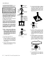
Page 31: ...himney See the Venting Arrangements chart below for minimum and maximum flue lengths See chart below for minimumdistancesfromroof Periodicallycheck that the vent is unrestricted Masonry chimneys may t...

Page 32: ...the vertical centerline Note if the centerline cannot be met the adjustable sections will have to be cut e Cut the 4 ft section of rigid pipe to length Attach the 45o elbow to the rigid pipe and ensu...

Page 33: ...e 4 dia starter collar 8 Cut the 4 dia flex liner to the desired size Hint leave an extra 12 to 16 of length this will make the final assembly easier to work with 9 Secure the 4 dia flex liner to the...

Page 34: ...he unit to the wall It is also important to note the wall thickness The wall thimble is suitable for 2 x 4 or 2 x 6 wall construc tion Select the amount of vertical rise desired for vertical to horizo...

Page 35: ...l Terminations For installations requiring a vertical rise on the exterior of the building 14 inch and 36 inch tall Snorkel Terminations and the Riser Vent as shown in Diagrams 2 2a are available Foll...

Page 36: ...p of 1 1 4 inches Secure the connection between the vent pipe and the vent cap by attaching the two sheet metal strips extending from the vent cap assembly into the outer wall of the vent pipe Use the...

Page 37: ...half of the flashing is in stalled under the roofing material and not nailed down until the chimney is installed This allows for small adjustments 6 Continue to assemble pipe lengths Note If an offset...

Page 38: ...intake is not covered under the ANSI Z21 88a 10007 CSA2 33a 10007testmethodsandtheresulting ITS WHIproductcertification ThecodeAuthor ityHavingJurisdictionmustbeconsultedprior to proceeding with this...

Page 39: ...hedral Ceilings Round Support RDS Square Support SQS If your home has a cathedral ceiling no attic space betweentheceilingandtheroof installthechimney and support as follows 1 Situate the chimney in a...

Page 40: ...r turn off the unit disconnect the hose and tighten the screw clockwise with a 1 8 flat screwdriver Note Screw should be snug but not over tightened Caution Carbon will be produced if the air shutter...

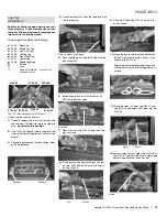
Page 41: ...fice with the allen key and replace with the LP pilot orifice in the kit and replace pilot cap 7 Remove burner orifice with a 1 2 wrench and discard Use another wrench to hold on to the elbow behind t...

Page 42: ...rst by carefully slipping it between the back wall of the firebox and the rear log bracket Back Panel Diagram 1 4 Before installing the side brick panels loosen the screws for the brick tabs enough so...

Page 43: ...02 46 G 02 48 C 02 44 B 02 56 F 02 47 E 02 45 Embers Embers C 02 44 Pins on Rear Log Support A 02 43 B 02 56 4 Place Rear Log A 02 43 on the two pins on the rear log support 5 Place the Middle Left L...

Page 44: ...on an interior wall Hampton offersanoptionalprogrammablethermo stat but any 250 750 millivolt rated non anticipator type thermostat that is CSA ULC or UL approved may be used CAUTION Do not connect t...

Page 45: ...e away from sharp edges WARNING Electrical Grounding Instructions This appliance is equipped with a three pronged grounding plug for your protection against shock hazard and should be plugged directly...

Page 46: ...46 Hampton H35E 11 Direct Vent Freestanding Gas Stove operating instructions Wiring Diagram with Optional thermostat RESET SWITCH Thermostat Optional Millivolt...

Page 47: ...de on a wall and carry out all the functions of a typical millivolt wall thermostat as well as being able to control the fan speed accent light and the flame height This is the recommended procedure f...

Page 48: ...tive ignition the board will go into lock out The system will need to be reset as follows a Wait 5 minutes turn the system off by pressing the ON OFF button on the remote b After approximately 2 secon...

Page 49: ...cet appareil s il a t plong dans l eau m me partiellement Faites inspecter l appareil par un technicien qualifi et remplacez tout l ment du syst me de contr le ou de commande qui a t plong dans l eau...

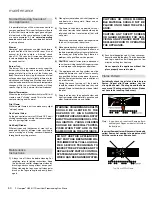
Page 50: ...TO THE HAZARDS OF HIGH SURFACE TEMPERATUREANDSHOULDSTAY AWAYTOAVOIDBURNSORCLOTH ING IGNITION YOUNG CHILDREN SHOULD BE CAREFULLY SUPER VISED WHEN THEY ARE IN THE SAME ROOM AS THE APPLIANCE 8 Each time...

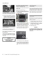
Page 51: ...placement Theunitshouldneverbeusedwithbrokenlogs Turn off the gas valve and allow the unit to cool before opening door to carefully remove the logs The pilot light generates enough heat to burn someon...

Page 52: ...ff electrical supply 3 Lift off cast top and place on a soft surface 4 Loosen bolts securing cast front slide light as sembly bracket upward to release 5 Remove two 2 screw to remove bulb housing Lift...

Page 53: ...e EV2 f yellow ground wire located under where orange wire was disconnected on gas valve 6 Lift off the Cast Top and lift out the front door 7 Removethecastfront Seepage13forinstruc tions 8 Remove the...

Page 54: ...the list should be checked by a licensed gas service technician during the annual service check Your unit may require more frequent maintenance checks if you notice any changes in how it operates Oper...

Page 55: ...ide Sand 15 743 211 Cast Left Charcoal Grey 743 215 Cast Left Timberline Brown 743 217 Cast Left Seaside Sand 16 743 221 Cast Right Charcoal Grey 743 225 Cast Right Timberline Brown 743 227 Cast Right...

Page 56: ...ilot Hood 2 way 910 432 Pilot Tube with Nut 911 137 Pilot Hood Clip 911 037 Flame Sensor 911 038 Flame Electrode 92 904 240 Burner Orifice 37 NG 92 904 390 Burner Orifice 52 LP 904 529 5 32 Allen Key...

Page 57: ...Hampton H35E 11 Direct Vent Freestanding Gas Stove 57 notes...

Page 58: ...Control Boards Wiring Switches Blowers Blower Control Module Battery Pack Remote Control Systems 2 Enamel Panels 1 Venting Venting Components 1 All Stainless steel surrounds 1 All Firebox Media Cryst...

Page 59: ...ndrafts installation error installation by an unqualified installer incorrect chimney components including but not limited to cap size or type operator error abuse misuse use of improper fuels lack of...

Page 60: ...de the U S should consult their local provincial or national legal codes for additional terms which may be applicable to this warranty How to Obtain Warranty Service Customers should contact the autho...

Page 61: ...low in order for us to serve you better Warranty Registration Form or Register online immediately at the above Web Site Warranty Details Serial Number required Purchase Date required mm dd yyyy Produc...

Page 62: ...62 Hampton H35E 11 Direct Vent Freestanding Gas Stove...

Page 63: ...Hampton H35E 11 Direct Vent Freestanding Gas Stove 63...

Page 64: ...wing information Dealer Name Address _______________________________________________ ___________________________________________________________________ Installer _____________________________________...

Reviews: