background image

10  | 

HI1150 Hampton Wood Cast Insert

installation

Installation Into a Factory-

built Fireplace

1.  When installed in a factory built fireplace, a 

full stainless steel rigid or flexible flue liner is 

mandatory,  for  both  safety  and  performance 

purposes.  When a flue or liner is in use, the 

insert is able to breathe better by allowing a 

greater draft to be created.  The greater draft 

can decrease problems such as, difficult start-

ups, smoking out the door, and dirty glass.  

2.  In order to position the flue liner, the existing 

rain cap must be removed from your chimney 

system. In most cases the flue damper should 

also be removed to allow passage of the liner.

3.  In  most  cases  opening  the  existing  spark 

screens fully should give enough room for the 

insert installation. If it does not, remove and 

store.

When  referencing  installation  or  connec-

tion  to  masonry  fireplaces  or  chimneys, 

the masonry construction must or shall be 

code complying.

Installation Into a 

Masonry Fireplace

The insert must be installed as per the requirements 

of your local inspection authority.  

In Canada this fireplace insert must be in-

stalled with a continuous chimney liner of 5.5" 

(140mm) or 6" (152mm) diameter extending 

from  the  fireplace  insert  to  the  top  of  the 

chimney. The chimney liner must conform to 

the Class 3 requirements of CAN/ULC-S635 or 

CAN/ULC-S640, Standard for Lining Systems 

for New Masonry Chimneys.

4.  If the floor of your fireplace is below the level 

of  the  fireplace  opening,  adjust  the  insert's 

levelling bolts to accommodate the difference. 

When  additional  shimming  is  required,  use 

non-combustible masonry or steel shims.

5.  Measure approximately the alignment of the 

flue liner with the position of the smoke outlet 

hole on the insert to check for possible offset. 

If  an  offset  is  required,  use  the  appropriate 

offset adaptor in your installation.

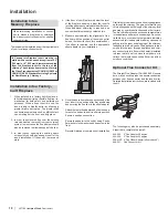
6.  Once the above items have been checked, slide 

your insert into position after first positioning 

and securing the flue liner to the offset adaptor. 


Attach the rod to the adaptor and slide the adap-

tor onto the unit as the unit is slid into position. 

Ensure a positive connection.


Secure the adaptor to the unit by using 2 bolts, 

flat washers, lock washers and one screw in the 

front.


Re-install raincap at completion of installation.

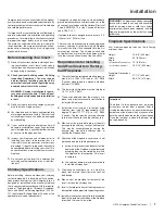
Draft is the force which moves air from the appliance 

up through the chimney. The amount of draft in your 

chimney depends on the length of the chimney, local 

geography, nearby obstructions and other factors. 

Too much draft may cause excessive temperatures 

in the appliance and may cause damage. An uncon-

trollable burn or excessive temperature indicates 

excessive draft. Inadequate draft may cause back 

puffing into the room and plugging of the chimney. 

Inadequate draft will cause the appliance to leak 

smoke into the room through appliance and chim-

ney connector joints. Ensure the heater is installed 

in areas that are not too close to neighbors or in 

valleys that would cause unhealthy air quality or 

nuisance conditions.

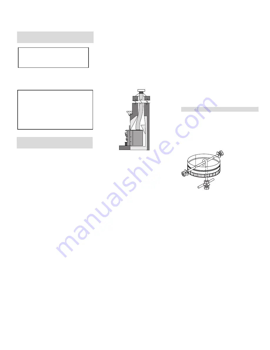
Optional Flue Connector Kit

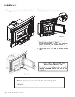
The Straight Flue Adaptor (Part  #846-504) shown 

here, may be used to produce a secure connection 

between your flue connector and the insert collar. 

Detailed installation instructions are included with 

the kit.

The following may also be purchased separately 

if required to complete the install:


846-506   6" Flue Adaptor-30 degree 

846-508   6" Flue Adaptor-45 degree 

948-412/P  6" Flue Offset Adaptor (offsets back 4") 

846-527   Flue Connector Kit

Summary of Contents for HI1150

Page 1: ...sert 06 17 20 Owner s Installation Manual Tested by Installer Please complete the details on the back cover and leave this manual with the homeowner Homeowner Please keep these instructions for future...

Page 2: ...hin the building envelope It is against federal regulation to operate this wood heater in a manner inconsistent with operating instructions in this manual This heater is designed to burn natural wood...

Page 3: ...affle Installation 14 Stainless Steel Smoke Deflector Installation 15 Operating Instructions Seasoned Wood 16 Operating Instructions 17 Draft Control 17 First Fire 17 Fan Operation 18 Ash Disposal 19...

Page 4: ...l DATE OF MANUFACTURE DATE DE FABRICATION MADE IN CANADA FAIT AU CANADA A D B C MUR LAT RAL ADJACENT PI CES OBLIGATOIRES POUR L INSTALLATION GAINE DE CHEMIN E HOMOLOGU E EN ACIER INOXYDABLE DE 5 5 PO...

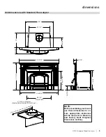
Page 5: ...sure appropriate clearances will be met refer to Masonry and Factory Built Fireplace Clearances section Unit Dimensions with Standard Flue Adaptor 6 152mm Diameter STANDARD FLUE ADAPTOR 172 942 6 152m...

Page 6: ...5 6 3 8 14 1 16 25 NOTE BeforeassemblingyourInsert use these dimensions to en sure appropriate clearances will be met refer to Masonry and Factory Built Fireplace Clearances section 6 152mm Diameter O...

Page 7: ...y injury or even death The more you understand the way your Hampton Insert operates the more enjoyment you will ex perience from knowing that your unit is operating at peak performance Before Installi...

Page 8: ...r floor protection and hearth will meet the standards for clearance to combustibles Your hearth extension must be made from a non combustible material Extending 16 for US and 18 for Canada measured fr...

Page 9: ...pening it and lifting it off its hinges Be sure to protect your hearth extension with a heavy blanket or carpet scrap during the installation NOTE You will be required to purchase either the standard...

Page 10: ...sure approximately the alignment of the flue liner with the position of the smoke outlet hole on the insert to check for possible offset If an offset is required use the appropriate offset adaptor in...

Page 11: ...right side see Diagrams 1 2 Mounting Bracket Mounting Bracket Gasket Gasket 2 Slide the unit into position leaving partially out to allow for installation of the left and right side surrounds 3 Instal...

Page 12: ...er starting fire 8 Surround adjustments can be made up or down loosen 4 bolts shown on face of unit Diagram 7 and adjust Surround can also be adjusted left or right loosen 4 bolts shown in Diagram 3 a...

Page 13: ...ositions Do not use a grate LyTherm sheet Order of firebrick install a Rear Firebrick b Firebox floor install brick over LyTherm Sheet c Right and left side Firebricks Fire bricks Size 1 4 1 4 x 7 2 4...

Page 14: ...the air tubes by removing both the bottom right base brick and right side wall brick 5 Install left and right baffle brackets installation of left baffle bracket shown below Baffle Installation 4 Ins...

Page 15: ...osen both bolts and slide deflector downward push deflector to the back wall of the unit and manoeuver out Install new deflector and hand tighten bolts Ensure positive location of the deflector prior...

Page 16: ...s Softer woods like pine spruce and poplar aspen that is cut split and stacked properly in the early spring maybe be ready for burning in the fall Extremely hard woods like oak and maple and large pie...

Page 17: ...nish 6 During the first few days it may be more difficult to start the fire As you dry out your firebrick and your masonry flue your draft will increase 7 For those units installed at higher elevation...

Page 18: ...on again This is too allow the stove to reach it s optimum temperature To operate fan automatically push switch on the rightsideoffanhousingto Auto andsecondswitch on the left to either High or Low f...

Page 19: ...henrefuelling the fire 12 Do not connect your unit to any air distribution duct 13 This heater is designed to burn natural wood only Higher efficiencies and lower emis sions generally result when burn...

Page 20: ...ve and chimney system Have the chimney cleaned before the burning season and as necessary during the season as creosote deposits may build up rapidly Moving parts of your stove require no lubrication...

Page 21: ...er using the 4 screws Do not wrench down on the glass as this may cause the glass to break 7 Place door back on unit Door Removal When handling enamel parts please handle with care as they can be dama...

Page 22: ...ers removed Cleaning Maintaining Your Wood Stove 1 Raise or lower the latch by undoing the inner 2 bolts Adjust to desired location and retighten the 2 bolts make sure the door catch closes freely and...

Page 23: ...ps using a hammer tap vise grips from right to left until air tube is released from grip Remove 4 Remove top left and right metal retainers followed by the fragile three piece C Cast Baffles then remo...

Page 24: ...1 Remove 2 front secondary air tubes vermiculite baffles see manual for details 2 Loosen the two 7 16 bolts nuts to remove replace vertical baffle 3 Repeat steps to install new vertical deflector NOT...

Page 25: ...he paper by pulling The paper should not pull out easily if it does try adjusting the door latch if that doesn t solve the problem replace the door gasket Check and lubricate door hinge latch Use only...

Page 26: ...s Retainer Clips Screws set of 4 14 940 356 P Glass Replacement 15 936 238 Adhesive Tape Gasket 16 948 467 Hinge Pin Lower 17 210 561 Door Assembly Metallic Black no glass Part Description 210 565 Doo...

Page 27: ...6 5 3 7 2 ITEM NO PART NUMBER QTY DESCRIPTION 7 RD 14287 2 3 500 x2 2500 BRICK 6 RD 14286 2 4 250 x 8 000 x 30 DEG BRICK 5 802 147 1 3 500 x 4 500 BRICK 4 802 152 2 2 000 x 9 000 BRICK 3 902 111 3 9...

Page 28: ...ng 1 Catalyst Combustor 10 Years Prorated Venting Chimney 1 Screens 1 See specific warranty details in regards to the catalyst combustor in unit manual Conditions Warranty protects against defect in m...

Page 29: ...rrect chimney components including but not limited to cap size or type operator error abuse misuse use of improper fuels such as unseasoned cordwood mill ends construction lumber or debris off cuts tr...

Page 30: ...tal or consequential damages so the above limitations or exclusions may not apply to you Customers located outside the U S should consult their local provincial or national legal codes for additional...

Page 31: ...der for us to serve you better Warranty Registration Form or Register online immediately at the above Web Site Warranty Details Serial Number required Purchase Date required mm dd yyyy Product Details...

Page 32: ..._________________________________ ___________________________________________________________________ Installer ____________________________________________________________ Phone _____________________...

Reviews: