background image

9

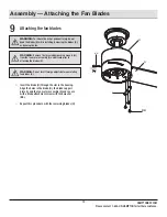
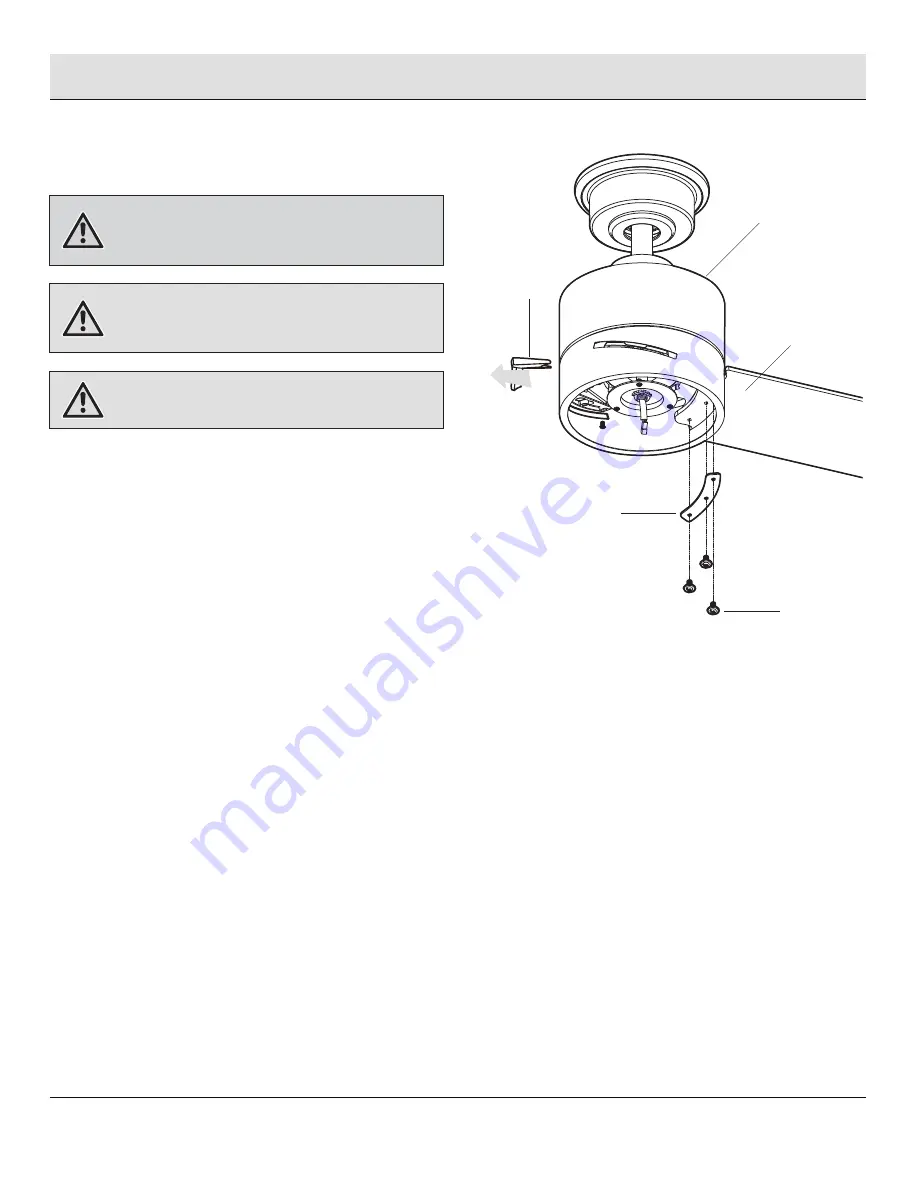
Assembly — Attaching the Fan Blades

15

WARNING:


To reduce the risk of personal injury, do not 

bend the blades (H) while installing, balancing the blades (H), 
or cleaning the fan.

Attaching the fan blades


Insert the blade (H) through the slot in the housing. 

Align the holes in the blade (H), the blade support 
plate (I), and the fan motor assembly (G) and secure 
with a blade attachment screw with lock washer 
(BB).


Repeat this procedure with the remaining blades (H).

BB

I

H

G

HAMPTONBAY.COM

Please contact 1-855-HD-HAMPTON for further assistance.

WARNING:


Remove the three rubber packing mounts (JJ) 

from the fan motor assembly (G) and discard prior to 
attaching the blades (H).

WARNING:


Do not insert foreign objects between rotating 

fan blades (H).

JJ

Summary of Contents for MADISON AK30A-BN

Page 1: ...ning to the store 8 a m 7 p m EST Monday Friday 9 a m 6 p m EST Saturday call Hampton Bay Customer Service Item 1005 131 715 Model AK30A BN Visual instruction of how to install this fan Visit www home...

Page 2: ...ounting Instruction Installation Assembly Standard Ceiling Mounting Close to Ceiling Mounting Hanging the Fan Attaching the Fan Blades Installing the Light Kit 2 3 4 4 4 4 5 6 7 8 9 9 10 11 15 16 Oper...

Page 3: ...the blades to the floor 5 Avoid placing objects in the path of the blades 6 To avoid personal injury or damage to the fan and other items be cautious when working around or cleaning the fan 7 Do not...

Page 4: ...ries is not covered by this warranty Because of varying climatic conditions this warranty does not cover any changes in brass finish including rusting pitting corroding tarnishing or peeling Brass fin...

Page 5: ...crew with lock washer not to scale Plastic wire nut not to scale 23A 12V battery not to scale Part Part Description Description 3 10 6 1 Quantity Quantity NOTE Hardware shown to actual size unless not...

Page 6: ...te 20W LED Light kit Glass shade Receiver Remote control Quantity Quantity 3 3 1 1 1 1 1 Part Part A B C D E F G Quantity Quantity 1 1 1 1 1 1 1 Description Description Mounting bracket preassembled C...

Page 7: ...standard downrod installation the distance from the ceiling to the bottom of the fan blades will be approximately 12 in The close to ceiling installation reduces the distance from the ceiling to the...

Page 8: ...t the outlet box not included Outlet Box Outlet Box Hanger Bar Outlet Box Recessed Outlet Box A Installation MOUNTING OPTIONS MOUNTING OPTIONS WARNING To reduce the risk of fire electric shock or pers...

Page 9: ...gn the holes at the bottom of the hanger ball downrod assembly E with the holes in the collar on top of the fan motor assembly G Carefully insert the clevis pin GG through the holes in the collar and...

Page 10: ...rew with lock washer EE on the top of the canopy C Remove the two non slotted canopy mounting screw with lock washer EE and loosen the slotted canopy mounting screw with lock washer EE Remove the cano...

Page 11: ...rting system marked acceptable for fan support and use the mounting screws provided with the outlet box WARNING The tab in the ring must rest in the groove of the hanger ball E Failure to properly sea...

Page 12: ...r M into the mounting bracket A with the flat side of the receiver M facing the ceiling NOTE The frequencies on your receiver and remote control have been preset at the factory Before installing the r...

Page 13: ...e black hot wire from the ceiling to the black wire marked AC in L from the receiver M Connect the white neutral wire from the ceiling to the white wire marked AC in N from the receiver M Connect the...

Page 14: ...to mounting Do not leave the fan assembly unattended until all four canopy mounting screw with lock washer EE are engaged and firmly tightened Make sure connections are neatly tucked into the ceiling...

Page 15: ...les in the blade H the blade support plate I and the fan motor assembly G and secure with a blade attachment screw with lock washer BB Repeat this procedure with the remaining blades H BB I H G HAMPTO...

Page 16: ...y removed CAUTION Before starting installation disconnect the power by turning off the circuit breaker or removing the fuse at the fuse box Turning power off using the fan switch is not sufficient to...

Page 17: ...witch is not sufficient to prevent electric shock Position the notches OO in the outer rim of the glass shade L so they line up with the tabs PP on the inside of the rim on the 20W LED light kit K Car...

Page 18: ...e button to turn the light on or off Press and hold the button to activate the dimmer function Correlated Color Temperature CCT changing Push and release the button to cycle through the three color te...

Page 19: ...ectrical shock Apply oil to your fan or motor The motor has permanently lubricated sealed ball bearings Do not Do not NOTE Wait for the fan to stop before reversing the direction of the blade rotation...

Page 20: ...bber isolator pads are used between the mounting bracket and outlet box The fan will not start The fan sounds noisy WARNING Make sure the power is off at the electrical panel box before you attempt an...

Page 21: ...er Fan motor assembly Blade Blade support plate Light kit mounting plate 20W LED Light kit Glass shade Receiver Remote control Part Part AA BB CC DD Description Description Plastic wire nut Blade atta...

Page 22: ...HAMPTON HAMPTONBAY COM Retain this manual for future use Questions problems missing parts Before returning to the store 8 a m 7 p m EST Monday Friday 9 a m 6 p m EST Saturday call Hampton Bay Customer...

Reviews: