background image


M

O

C

.

Y

A

B

N

O

T

P

M

A

H


3


 .

e

c

n

a

t

s

i

s

s

a

 r

e

h

t

r

u

r

o

3

1

3

0

-

7

2

5

-

7

7

8

-

1

 t

c

a

t

n

o

c


e

s

a

e

l

P


Warranty 


LIMITED LIFETIME WARRANTY

The supplier warrants the fan motor to be free from defects in workmanship and material present at time of shipment from the factory for a 
lifetime after the date of purchase by the original purchaser. The supplier also warrants that all other fan parts, excluding any glass or 

acrylic blades, be free from defects in workmanship and material at the time of shipment from the factory for a period of one year after 
the date of purchase by the original purchaser. We agree to correct such defects without charge or at our option replace with a comparable 

or superior model if the product is returned. To obtain warranty service, you must present a copy of the receipt as proof of purchase. All 
costs of removing and reinstalling the product are your responsibility. Damage to any part, such as by accident, misuse, improper 

installation, or by 

 any accessories, is not covered by this warranty. Because of varying climatic conditions, this warranty does not  

cover any changes in brass  nish, including rusting, pitting, corroding, tarnishing, or peeling. Brass finishes of this type give their longest 

useful life when protected from varying weather conditions. A certain amount of “wobble” is normal and should not be considered a defect. 
Servicing performed by unauthorized persons shall render the warranty invalid. There is no other express warranty. The supplier hereby 

disclaims any and all warranties, including but not limited to those of merchantability and 

 for a particular purpose to the extent 

permitted by law. The duration of any implied warranty which cannot be disclaimed is limited to the time period as 

 in the express 

warranty. Some states do not allow a limitation on how long an implied warranty lasts, so the above limitation may not apply to you. The 
retailer shall not be liable for incidental, consequential, or special damages arising out of or in connection with product use or performance 

except as may otherwise be accorded by law. Some states do not allow the exclusion of incidental or consequential damages, so the above 
exclusion or limitation may not apply to you. This warranty gives 

 legal rights, and you may also have other rights which vary from 

state to state. This warranty supersedes all prior warranties. Shipping costs for any return of product as part of a claim on the warranty 
must be paid by the customer. 

Contact the Customer Service Team at 1-877-527-0313 or visit www.HamptonBay.com. 

Pre-Installation 


PLANNING INSTALLATION 

Compare all parts with the Hardware Included and Package Contents sections in this manual. If any part is missing or damaged, do not 

install this fan and contact the Customer Service Team at 1-877-527-0313 or visit www.HamptonBay.com. 

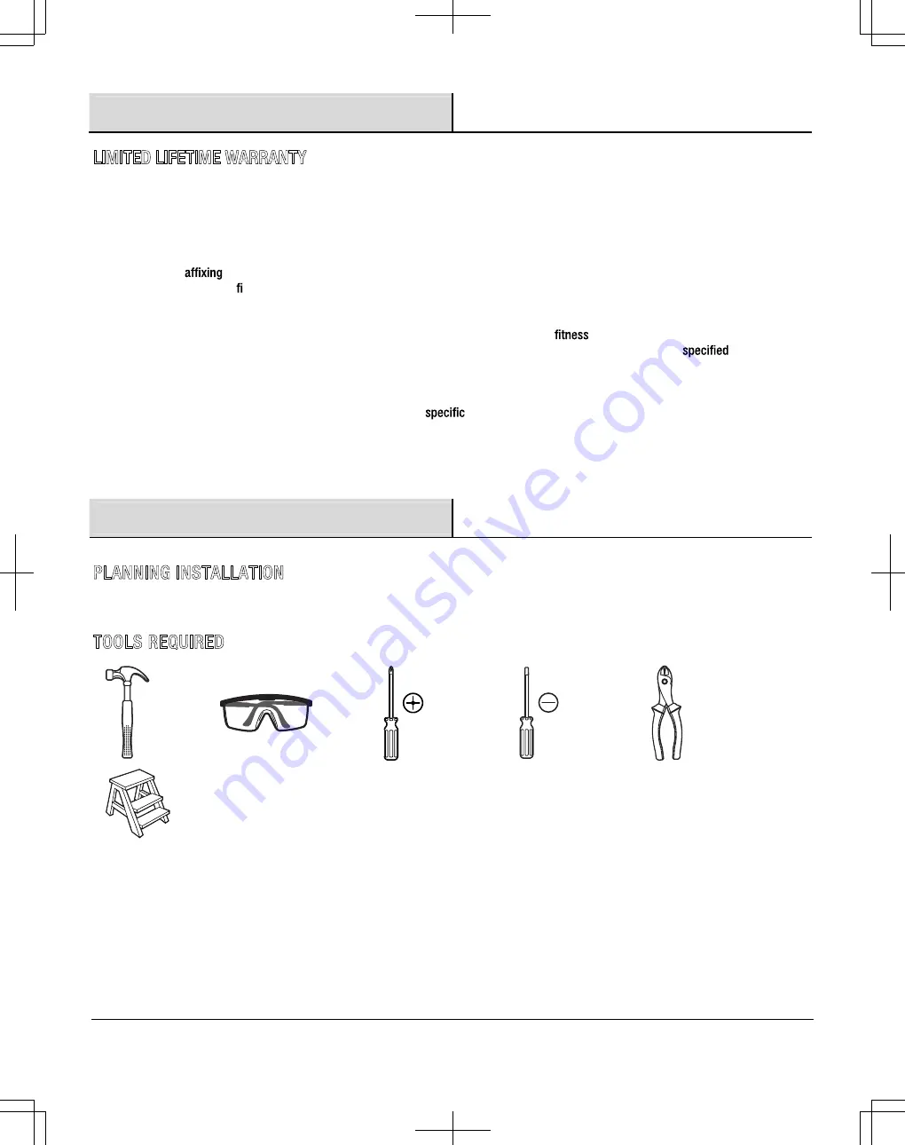
TOOLS REQUIRED 


Hammer 


Safety 

goggles 

Phillips 

screwdriver 

Flathead 

screwdriver 


Wire cutters 


Step 
ladder 


DPA12122003 新版 SIZE:216x280mm 80g模糙纸 28P 单黑色 骑马钉 2013-4-17  第 3/28页

Summary of Contents for MINNA HE-12026

Page 1: ...it us online to see our full line of products available for your home improvement needs Thank you for choosing Hampton Bay Item 602 651 Model HE 12026 USE AND CARE GUIDE MINNA CEILING FAN Questions pr...

Page 2: ...the fan must be UL listed and marked suitable for use with the model fan you are installing Switches must be UL General Use Switches Refer to the instructions packaged with the light kits and switche...

Page 3: ...by unauthorized persons shall render the warranty invalid There is no other express warranty The supplier hereby disclaims any and all warranties including but not limited to those of merchantability...

Page 4: ...ownrod D 1 DD Collar screw preassembled to Motor C 1 EE Washer 2 2 r e h s a w r a t S F F 2 r e h s a w k c o L G G 2 w e r c s t e k c a r b g n i t n u o M H H II Canopy screw preassembled to Mount...

Page 5: ...e s a e l P Pre Installation continued Part Description Quantity A Fan blade 4 4 Blade iron B 1 Fan motor C D Downrod 1 1 Canopy E 1 Upper housing F 1 Mounting bracket G 1 Light kit H 1 Bulb I 1 Glass...

Page 6: ...wer by removing the fuses or turning off the circuit breakers Secure the outlet box directly to the building structure Use the appropriate fasteners and materials The outlet box and its bracing must b...

Page 7: ...g the blade assemblies to the motor Preparing the downrod 4 Secure the blade irons B with the blades A to the motor C using the blade iron screws LL Remove the downrod clip BB and downrod pin CC from...

Page 8: ...rod pin CC through the holes in the collar 1 and downrod D Insert the downrod clip BB through the hole near the end of the downrod pin CC until it snaps into its locked position Re tighten the collar...

Page 9: ...ied with this fan is designed to accept up to one 12 gauge house ires from the fan If you have larger than 12 gauge house wiring or more than one house wire to connect to the fan wiring consult an ele...

Page 10: ...t remove two of the light kit screws JJ attached to the light kit plate 1 portion of the motor C Remove the third light kit screw JJ from the light kit plate 1 portion of the motor C Raise the light k...

Page 11: ...ling the pull chain pendant Connect the pull chain pendants K to the chains extending from the motor C Install the bulb I into the socket on the light kit H Raise the glass shade J up to the light kit...

Page 12: ...reverse switch left Warm weather Forward A do ow creates a cooling effect This allows you to set your air conditioner on a higher setting without affecting your comfort air off the ceiling area This a...

Page 13: ...e fan and switch wire connections in the switch housing The fan is noisy Ensure all motor housing screws are snug Ensure the screws that attach the fan blade bracket to the motor hub are tight Ensure...

Page 14: ...ssing parts Before returning to the store call Hampton Bay Customer Service 8 a m 6 p m EST Monday Friday 1 877 527 0313 HAMPTONBAY COM Retain this manual for future use DPA12122003 SIZE 216x280mm 80g...

Page 15: ...e calidad dise ados para mejorar su hogar Vis tenos en internet para ver nuestra l nea completa de productos disponibles para sus necesidades de mejorar su hogar Gracias por elegir a Hampton Bay Tiene...

Page 16: ...mo adecuados para uso con el ventilador modelo que est instalando Los interruptores deben ser Interruptores de Uso General UL Consulte las instrucciones que vienen con los juegos de l mparas e interru...

Page 17: ...proveedor se exime de cualquier garant a incluyendo pero no limitadas a garant as de comercializaci n e idoneidad para un prop sito particular en la medida permitida por la ley La duraci n de cualqui...

Page 18: ...trella F F 2 Arandela de seguridad G G 2 Tornillo de soporte de montaje H H II Tornillo de dosel preensamblado a soporte de montaje G 2 JJ Tornillo de juego de l mparas preensamblado a motor C 3 4 Con...

Page 19: ...oporte de montaje G 1 Juego de l mparas H 1 Bombilla I 1 Pantalla de vidrio J 2 Colgante del interruptor de cadena K A B C E I K J F G H D CONTENIDO DEL PAQUETE Descripci n Cantidad M O C Y A B N O T...

Page 20: ...con un electricista Si su ventilador de techo no tiene una caja de montaje existente listada UL entonces instale una empleando las siguientes instrucciones Desconecte la energ a retirando los fusibles...

Page 21: ...porte del aspa LL Retire el gancho del v stago de extensi n BB y el pasador del v stago de extensi n CC del v stago de extensi n D Ensarte el v stago de extensi n D a trav s del dosel E y la carcasa s...

Page 22: ...tago de extensi n D Inserte el gancho del v stago de extensi n BB a trav s del agujero cercano al extremo del pasador del v stago de extensi n CC hasta que encaje en su posici n bloqueada Apriete de n...

Page 23: ...de luces OO NN QQ PP OO QQ 1 PP C mo colgar el ensamblaje del ventilador C mohacerlasconexionesel ctricas D G M O C Y A B N O T P M A H e s a g n p a i c n e t s i s a r e n e t b o a r a P en contact...

Page 24: ...ador instalados en la parte de la placa 1 del juego de l mparas del motor C Retire el tercer tornillo JJ del juego de l mparas de la parte de la placa 1 del juego de l mparas del motor C Sube el kit d...

Page 25: ...llas I en los recept culos del juego de l mparas H Levante la pantalla de vidrio J hasta el juego de l mparas H alinee las pesta as en el juego de l mparas H con las ranuras en la pantalla J y gire ha...

Page 26: ...quierdo crea un efecto de enfriamiento Esto le permite ajustar su acondicionador de aire a un ajuste m s alto sin afectar su comodidad Clima fresco Reversa Una corriente de aire hacia arriba hace sali...

Page 27: ...lador hace ruido Aseg rese de que todos los tornillos de la carcasa del motor est n ajustados Aseg rese de que los tornillos que sujetan el soporte de las aspas del ventilador al n cleo del motor est...

Page 28: ...s Antes de regresar a la tienda llame al Servicio a Clientes de Hampton Bay entre 8 a m y 6 p m hora local del Este de lunes a viernes 1 877 527 0313 HAMPTONBAY COM Conserve este manual para uso futur...

Reviews: