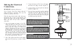
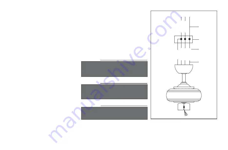
background image

7

SUPPLY CIRCUIT

Figure 13

BLACK WHITE

BLACK WHITE

BLUE

GREEN

Outlet Box

Ground

Conductor

Green

Ground

Lead
Ground to

Downrod

Making the Electrical 

Connections

WARNING

CHECK TO SEE THAT ALL CONNECTIONS ARE 

TIGHT, INCLUDING GROUND, AND THAT NO 

BARE WIRE IS VISIBLE AT THE WIRE NUTS. 

EXCEPT FOR THE GROUND WIRE.  

WARNING

ELECTRICAL DIAGRAMS ARE FOR REFER-

ENCE ONLY. OPTIONAL USE OF ANY LIGHT 

KIT SHALL BE NOM LISTED AND MARKED 

SUITABLE FOR USE WITH THIS FAN.

Connect the fan motor black wire to the supply 
black (hot) wire using a wire nut. (Figure 13)

Connect the blue wire for light kit to the black 
household supply wire.

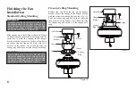
Turn wire nut connections upward, spreading 
them apart so the green (ground) will be on one 
side of the outlet box and the white, black and 
blue wire will be on the other side, and push 
carefully up into the outlet box.

3.

4.

5.

Connect the ground conductor of the 120V 
supply (this may be a bare wire or a wire with 
green colored insulation) to the green ground 
lead(s) of the fan. (Figure 13) When using 
standard ceiling mounting, there are two green 
grounding leads; one from the ceiling mount-
ing bracket and one from the ball/downrod 
assembly. When using “Flushmount Installa-
tion” mounting, there is only one green ground 
lead from the ceiling mounting bracket since 
the ball/downrod assembly is not used.

Connect the fan motor white wire to the supply 
white (neutral) wire using a wire nut. (Figure 
13)

1.

2.

REMEMBER

 to disconnect the power.

If you feel you do not have enough electrical 
wiring knowledge or experience, have your fan 
installed by a licensed electrician.

Follow the steps below to connect the fan to your 
household wiring. Use the wire nuts supplied with 
your fan. Secure the wire nuts with electrical tape. 
Make sure there are no loose strands or 
connections.

WARNING

TO REDUCE THE RISK OF FIRE OR ELECTRIC 

SHOCK. DO NOT USE THIS FAN WITH ANY 

SOLID-STATE SPEED CONTROL DEVICE.

Summary of Contents for Minuet III AG806C-EB

Page 1: ...III 36 in Ceiling Fan Owner s Manual Minuet III Ventilador de Techo de 91 4 cm Manual del Propietario 122 888 Model AG806C EB 120 V 60 Hz 110 W Read and follow all the instructions before using this p...

Page 2: ...Minuet III by Hampton Bay...

Page 3: ...VICIOS HOME DEPOT S DE R L DE C V Ricardo Margain 605 Santa Engracia San Pedro Garza Garc a Nuevo Le n C P 66267 Tel Phone 01 800 004 6633 Lea y siga todas las instrucciones de seguridad y operaci n a...

Page 4: ...or purchasing our ceiling fan This product has been manufactured with the highest standards of safety and quality Table of Contents Safety Rules 1 Unpacking Your Fan 2 Installing Your Fan 3 Installing...

Page 5: ...le for most cleaning 1 2 3 4 5 6 7 8 9 After making electrical connections spliced conductors should be turned upward and pushed carefully up into outlet box The wires should be spread apart with the...

Page 6: ...2 3 4 5 Set of blade arms 6 Light fixture Glass shade Pull chain and fobs 2 Extra plastic plug 6 7 8 9 10 Blade Attachment Hardware 19 Screws with fiber Washers Electrical Hardware 3 Plastic Wire Nuts...

Page 7: ...SCREWS PROVIDED WITH THE OULET BOX OUTLET BOX COMMONLY USED FOR THE SUPPORT OF LIGHTING FIXTURE MAY NOT BE ACCEPTABLE FOR FAN SUPPORT AND MAY NEED TO BE REPLACED CONSULT A QUALIFIED ELECTRICIAN IF IN...

Page 8: ...NING AND POSSIBLY FALLING Figure 7 Remove the Canopy Ring Figure 5 Loosen but do not remove Remove Figure 6 Remove the canopy ring from the canopy Figure 5 1 Remove the mounting bracket from the canop...

Page 9: ...ires exiting the top of the fan motor through the canopy ring make sure the slot openings are on top then proceed to place the ceiling canopy over the collar at the top of the motor Figure 10 Align th...

Page 10: ...Carefully lift the fan assembly up to the ceiling mounting bracket and hang the fan on the tab provided by utilizing one of the holes at the outer rim of the ceiling canopy Figure 12 If use standard...

Page 11: ...the ground conductor of the 120V supply this may be a bare wire or a wire with green colored insulation to the green ground lead s of the fan Figure 13 When using standard ceiling mounting there are...

Page 12: ...LL FOUR CANOPY SCREWS ARE ENGAGED AND FIRMLY TIGHTENED Slide canopy up to the ceiling as shown in Figure 14 Make sure you place the wires safely into the outlet box Secure the canopy to the hanger bra...

Page 13: ...unts Screws Blade Screws with Fiber Washers Blade Arm Motor Blade Arm Slot Tab Figure 18 Figure 16 Attach blades to blade arms using three screws with fiber washers Fig 17 Start a screw into the blade...

Page 14: ...as shown in Figure 19 Rotate the fan until the next blade is positioned and repeat the measurement using the same point from the ceiling for every blade Measurement deviations should be within 1 8 If...

Page 15: ...en all screws Fig 20 Install 60 watt Max medium base bulb not included Fig 20 Mount the glass shade to the light fixture by unscrewing partway the thumbscrews on the glass holder insert the glass then...

Page 16: ...operation of the fan The pull chain controls the fan speed as follows 1 pull High 2 pulls Medium 3 pulls Low 4 pulls Off Light kit pull chain it controls the light kit in ON or OFF Speed settings for...

Page 17: ...olish There is no need to oil your fan The motor has permanently lubricated sealed ball bearings 1 2 3 4 Here are some suggestions to help you maintain your fan Check main and branch circuit fuses or...

Page 18: ...267 Tel 01 800 004 6633 Warranty printed on manual is not valid for Mexico Questions problems missing parts Before returning to the store call our customer service 01 800 004 6633 0 17 0 27 0 33 9 90...

Reviews: