background image

10

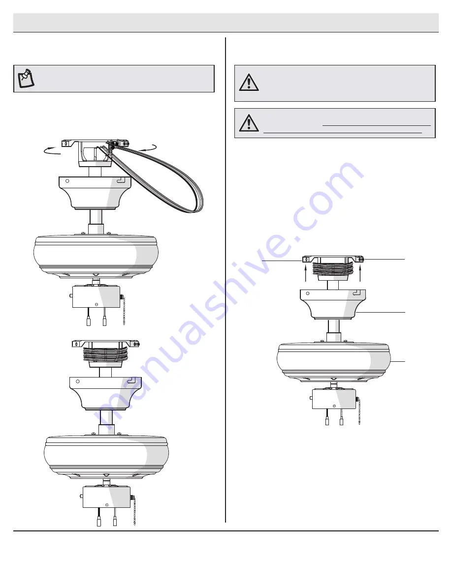
Assembly - Hanging the Fan (continued)

Mounting the fan-motor assembly 
(standard mount)

4

D

A

II

C

5

Wrapping the extra wire


Gently wrap the excess wire around the mounting bracket.


Secure with electrical tape.

NOTE:

 Follow this step ONLY if you did not cut the extra length off 

from the wires coming from the ceiling fan.


Align the locking slots of the ceiling canopy (C) with the two 
screws (II) in the mounting bracket (A). Push up to engage the 
slots and turn clockwise to lock in place.


Firmly tighten the two mounting screws.


Install the two mounting screws (saved from Assembly Step 
1 “Prepairing for mounting”) into the holes in the canopy (C) 
and tighten firmly.

WARNING:

 When using the standard ball/downrod mounting, the 

tab in the ring at the bottom of the mounting bracket must rest in 

the groove of the hanger ball. Failure to properly seat the tab in 

the groove could cause damage to the wiring.

WARNING:

 The locking slots of ceiling canopy are provided only 

as an aid to mounting. Do not leave the fan assembly unattended 

until all four canopy screws are engaged and firmly tightened.

Summary of Contents for ROTHLEY 51563

Page 1: ...er Service 8 a m 6 p m EST Monday Friday 1 855 HD HAMPTON HAMPTONBAY COM THANK YOU We appreciate the trust and confidence you have placed in Hampton Bay through the purchase of this ceiling fan We str...

Page 2: ...installing Switches must be UL General Use Switches Refer to the instructions packaged with the light kits and switches for proper assembly 9 After making electrical connections spliced conductors sho...

Page 3: ...er the warranty invalid There is no other express warranty Hampton Bay hereby disclaims any and all warranties including but not limited to those of merchantability and fitness for a particular purpos...

Page 4: ...wire connector 3 CC Hanger pin 1 DD Locking pin 1 EE Rubber gasket 1 Part Description Quantity FF Plastic Plug to be used for fan without light kit 1 GG Pull chain 2 Pre Installation continued HARDWAR...

Page 5: ...Light kit fitter assembly 1 Part Description Quantity F Blade 5 G Blade bracket with pre installed screws 5 H Shatter resistant bowl 1 I LED bulbs 9 5 Watt Maximum 2 IMPORTANT This product and or com...

Page 6: ...he appropriate fasteners and materials The outlet box and its bracing must be able to fully support the weight of the moving fan at least 35 lbs Do not use a plastic outlet box The illustrations below...

Page 7: ...nrod assembly B Insert the locking pin DD through the hole near the end of the hanger pin CC until it snaps into its locked position Re tighten the setscrews JJ on the collar on top of the fan motor a...

Page 8: ...bracket A on the outlet box by sliding the slide on mounting bracket A over the two screws LL provided with the outlet box If necessary use leveling washers not included between the slide on mounting...

Page 9: ...electrical tape and ensure there are no loose strands or connections WARNING Each wire not supplied with this fan is designed to accept up to one 12 gauge house wire and two wires from the fan If you...

Page 10: ...slots and turn clockwise to lock in place Firmly tighten the two mounting screws Install the two mounting screws saved from Assembly Step 1 Prepairing for mounting into the holes in the canopy C and t...

Page 11: ...ush up to engage the slots and turn clockwise to lock in place Immediately tighten the two mounting screws firmly Install the two mounting screws saved from Assembly Step 1 Prepairing for mounting int...

Page 12: ...rews V V on the switch cup cover of the light kit fitter assembly E Connect the wires from the light kit fitter assembly E to the wires from the switch cup of the fan motor assembly D by connecting th...

Page 13: ...ter resistant bowl to cool completely before removing I D E H GG CAUTION Do not over tighten the hex nut overtightening the hex nut may cause the shatter resistant bowl to break D WW V V FF GG Assembl...

Page 14: ...n of the blades forward switch down or reverse switch up A Warm weather Forward A downward airflow creates a cooling effect This allows you to set your air conditioner on a higher setting without affe...

Page 15: ...the ceiling above the tip of one of the blades Measure from a point on the center of each blade to the point on the ceiling Measure this distance Rotate the fan until the next blade is positioned for...

Page 16: ...Questions problems missing parts Before returning to the store call Hampton Bay Customer Service 8 a m 6 p m EST Monday Friday 1 855 HD HAMPTON HAMPTONBAY COM Retain this manual for future use...

Reviews: