3
9. Any guard or other protective device removed for servicing the heater must be replaced prior to operating the heater.
annually by a
11. More frequent cleaning may be required as necessary. It is imperative that control compartment, burners and circulating air passageways
of the heater be kept clean.
14. Keeping the ventilation opening(s) of the cylinder enclosure free and clear from debris.
15. This appliance shall be used only in a well-ventilated space and shall not be used in a building, garage or any other enclosed area.
16. An appliance may be installed with shelter no more inclusive than:
17. With walls on all sides, but with no overhead cover.
18. Within a partial enclosure which includes an overhead cover and no more than two side walls. These side walls may be parallel, as in a
breezeway, or at right angles to each other
19. Within a partial enclosure which includes an overhead cover and three side walls, as long as 30 percent or more of the horizontal periphery
of the enclosure is permanently open.
ders of the
U.S.
21. Department of Transportation (DOT); or the Standard for Cylinders, Spheres and Tubes for Transportation of Dangerous Goods and
Commission, CAN/CSA-B339, as applicable;
nection for the
appliance.
23. The cylinder be disconnected when the appliance is not in use.
24. Storage of an appliance indoors is permissible only if the cylinder is disconnected and removed from the appliance.
25. A cylinder must be stored outdoors in a well-ventilated area out of the reach of children. A disconnected cylinder must have dust caps tightly
installed and must not be stored in a building, garage or any other enclosed area.
26. The pressure regulator and hose assembly supplied with the appliance must be used, replacement pressure regulators and hose assemblies
28. Do not clean the heater with cleaners that are combustible or corrosive.
29. Place the dust cap on the cylinder valve outlet whenever the cylinder is not in use. Only install the type of dust cap on the cylinder valve that
is provided with the cylinder valve. Other types of caps or plugs may result in leakage of propane
30. Certain materials or items, when stored under the heater, will be subjected to radiant heat and could be seriously damaged.
31. Inspect the visible portion of the hose before each use of the appliance and inspect the entire hose assembly at lease annually.
32. The cylinder used must include a collar to protect the cylinder valve.
Safety Information
(Continued)
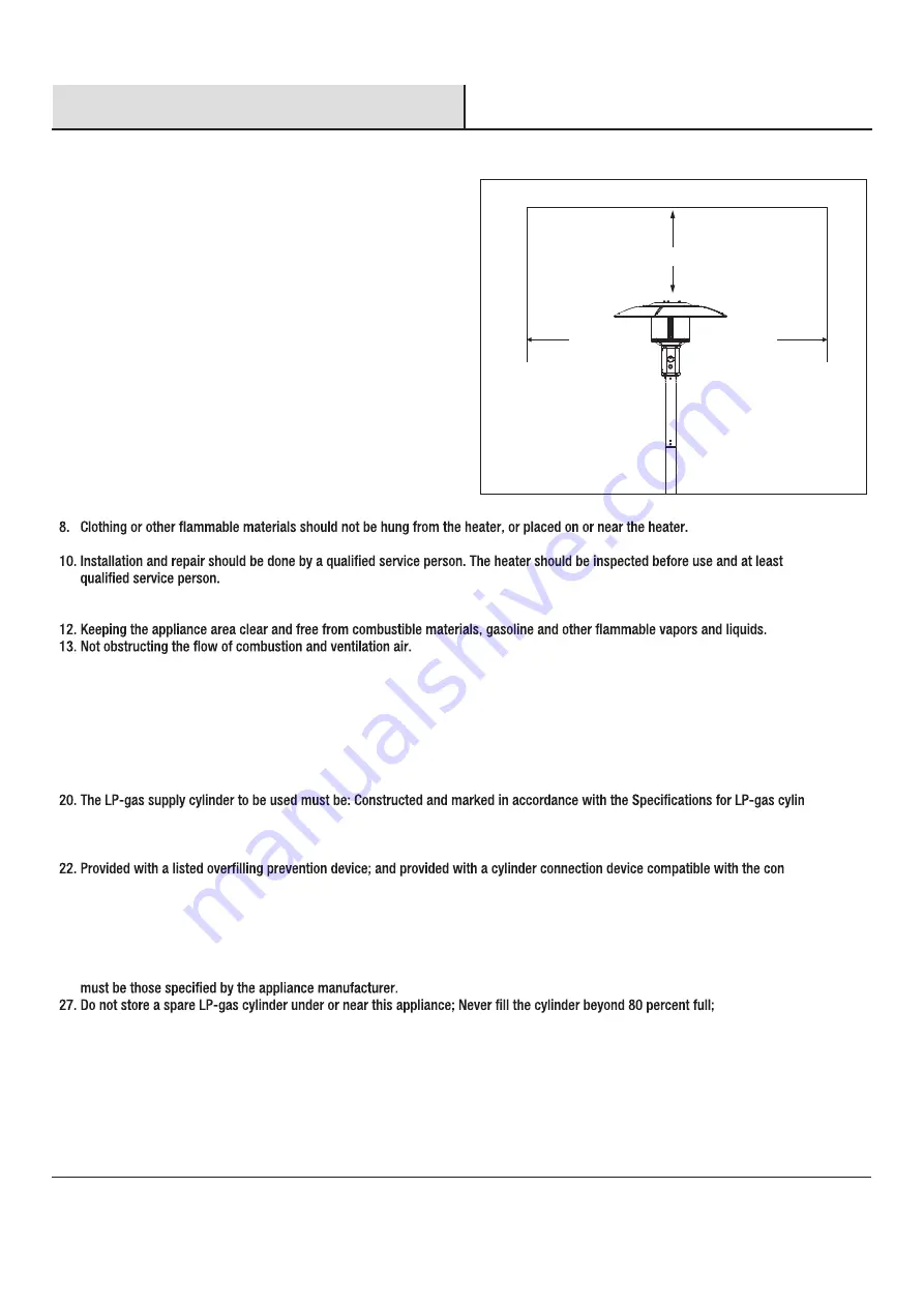
CEILING/OVERHANG
1. The installation must conform with local codes or, in the absence of
local codes, with the National Fuel Gas Code, ANSI Z223.1/NFPA 54,
NFPA58 Natural Gas and Propane Installation Code, CSA B149.1, or
Propane Storage and Handling Code, B149.2
2. The heater, when installed, must be electrically grounded in
accordance with local codes or, in the absence of local codes, with
the National Electrical Code, ANSI/NFPA 70, or the Canadian Electrical
Code, CSA C22.1.
3. Prior to use, check for damaged parts such as hoses, regulators, pilot
or burner.
4. All leak tests should be done with a soapy solution.NEVER USE AN
OPEN FLAME TO CHECK FOR LEAKAGE.
5. The propane hose with regulator assembly shall be located out of
pathways where people may trip over it or in areas where the hose
will not be subject to accidental damage.
6. Children and adults should be alerted to the hazards of high surface
temperatures and should stay away to avoid burns or clothing ignition.
7. Young children should be carefully supervised when they are in the
area of the heater.
36 in.
.
n
i
6
3
.
n
i
6
3
Figure 1
WA
LL


