background image


M

O

C

.

Y

A

B

N

O

T

P

M

A

H


8


 .

e

c

n

a

t

s

i

s

s

a

 r

e

h

t

r

u

r

o

f

N

O

T

P

M

A

H

-

D

H

-

5

5

8

 t

c

a

t

n

o

c


e

s

a

e

l

P


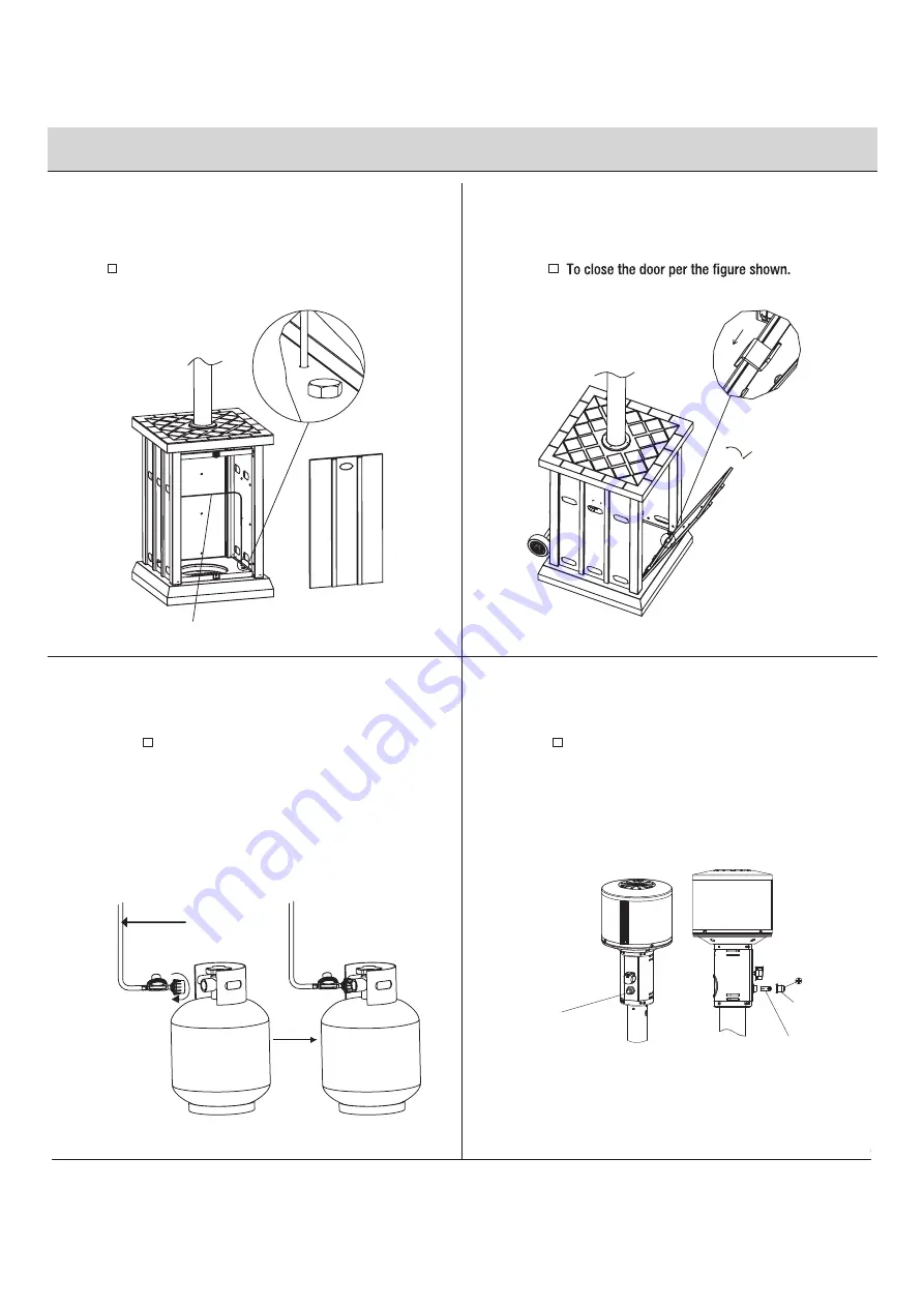
Assembly  

(continued)    


9

Place Gas Cylinder

11

 Close the Door

10

Install Regulator


Place the gas cylinder (not included) into the base (G) and 
secure with the cylinder locking bar (H).

Attach the regulator to the cylinder and turn 
clockwise to securely tighten the valve. Close and 
latch the door. Note: Make sure to check for leaks 
after attaching the cylinder. (For instructions, refer 
to the page14-SAFETY CHECK) To remove the 
regulator, turn off the cylinder valve and turn 
counterclockwise the regulator to loosen from the 
cylinder.

12

Install Battery


Unscrew the battery compartment cap on the control 
panel, install one AAA battery (not included) with 
anode end of battery located towards the battery 
compartment cap.

M

Tighten

gas hose and regulator

ignition button

ignition button

AAA battery

(not included)

Summary of Contents for SRPH78

Page 1: ...ucts available for your home improvement needs Thank you for choosing Hampton Bay Item Model SRPH78 USE AND CARE GUIDE Devonport tile top Patio Heater Questions problems missing parts Before returning...

Page 2: ...ller Leave the instruction manual to the user for future use Consumer Please keep this manual for future reference NOTE PLEASE READ THE FOLLOWING SAFETY RULES Perform a leak test with a soapy solution...

Page 3: ...bly supplied with the appliance must be used replacement pressure regulators and hoseassemblies 28 Do not clean the heater with cleaners that are combustible or corrosive 29 Place the dust cap on the...

Page 4: ...SUSTANCIAS QU MICAS ENTRE ELLAS EL BENCENO QUE EL ESTADO DE CALIFORNIA RECONOCE COMO CAUSA DE C NCER Y DE MALFORMACIONES CONG NITAS Y OTROS DA OS AL SISTEMA REPRODUCTOR Para m s informaci n visite www...

Page 5: ...S CC BB AA DD EE A B C D E F G GG HH H I FF EE J Quantity Description Part Center Reflector Cap Reflector Shields Burner Head Upper Pole Lower Pole Decorative Cap A B C D E F G 1 4 1 1 1 1 1 1 1 1 Bas...

Page 6: ...the lower pole E to cover the bolts Note When you assemble lower pole to the base please 4 Install Upper Pole Insert gas hose and regulator of the burner head C into the lower pole E Place the upper p...

Page 7: ...c a t n o c e s a e l P Assembly continued 5 7 6 Place Bolt AA 12 6mm washers BB and 12 M6 nuts CC Thread 3 6mm washers BB and 3 M6 x 70 double pointed bolts DD into the burner head C 8 Open the Door...

Page 8: ...urely tighten the valve Close and latch the door Note Make sure to check for leaks after attaching the cylinder For instructions refer to the page14 SAFETY CHECK To remove the regulator turn off the c...

Page 9: ...pection of the entire gas path components should be performed If there is need to replace parts proceed to leak test after reassembly These procedures should be performed by a professional technician...

Page 10: ...peration LIGHTING INSTRUCTION 1 Turn the control knob to OFF position 2 Turn LP cylinder gas valve to fully open position 3 Push in gas control knob and turn counter clockwise to PILOT position at the...

Page 11: ...sed to water in any way do NOT try to use it It must be replaced of combustion and ventilation air keeping the ventilation opening s of the cylinder enclosure free and clear from debris Screw down the...

Page 12: ...D H 5 5 8 t c a t n o c e s a e l P Service Parts MODEL TYPE CC BB AA DD EE A B C D E F G GG HH H I FF EE J Quantity Description Part Burner Head Upper Pole Lower Pole Decorative Cap A B C D E F G 1 4...

Page 13: ...TON HAMPTONBAY COM Retain this manual for future use Questions problems missing parts Before returning to your retailer call our customer service department 8 a m 6 p m EST Monday Friday 9 a m 6 p m E...

Reviews: